
Steel bar bending mechanism applied to automatic hoop bending machine

A technology of steel bar bending mechanism and hoop bending machine, which is applied in the field of steel bar bending mechanism, and can solve problems such as prone to arching, difficult positioning of steel bars, and improper bending

Active Publication Date: 2020-10-27
CHINA METALLURGICAL CONSTR ENG GRP
View PDF4 Cites 1 Cited by
  • Summary
  • Abstract
  • Description
  • Claims
  • Application Information

AI Technical Summary

Problems solved by technology

After this setting, it is difficult to position the steel bar during the bending process, and it is prone to arching, or the bending is not in place, which will affect the next continuous operation of the bending mechanism

Method used


Image

  • Steel bar bending mechanism applied to automatic hoop bending machine
  • Steel bar bending mechanism applied to automatic hoop bending machine
  • Steel bar bending mechanism applied to automatic hoop bending machine

Examples


Embodiment

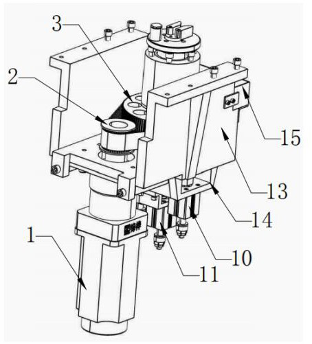
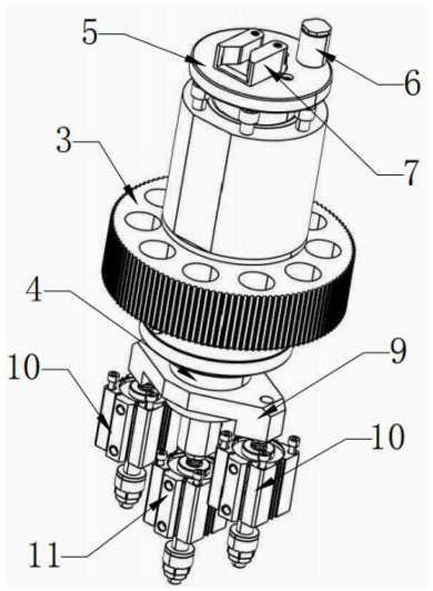
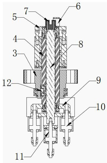
[0025] Such as Figure 1-Figure 3As shown, the steel bar bending mechanism applied to the automatic hoop bending machine provided by this embodiment includes a rotating motor 1 and a bending head 5 that can rotate circumferentially under the drive of the motor 1. A vertical bending head 5 is detachably mounted on the bending head 5. The movable bending bar 6 that is provided with; Next to the movable bending bar 6, there is also a steel bar locator 7 whose lower end runs through the bending head 5, and a steel bar locating groove 74 is arranged in the middle of the steel bar locating piece 7; The hollow outer shaft 4 arranged vertically, the hollow outer shaft 4 can be rotated under the drive of the bending motor 1, and after driving the movable bending rod 6 to rotate synchronously, the steel bar protruding out of the steel bar positioning groove 74 will be folded according to the set angle Bending, when bending, the steel bar positioning part 7 forms a steel bar tight part n...


PUM


Abstract

The invention discloses a steel bar bending mechanism applied to an automatic hoop bending machine. The mechanism comprises a rotating motor and a bending head capable of rotating in the circumferential direction driven by the motor, and a movable bending rod is detachably mounted on the bending head; a steel bar positioning part is detachably installed on the bending head, beside the movable bending rod, and a steel bar positioning groove is formed in the middle of the steel bar positioning part; a vertically arranged hollow outer shaft is fixedly installed under the bending head, the hollowouter shaft can rotate driven by a bending motor, and drive the movable bending rod to rotate synchronously, steel bars protruding out of the steel bar positioning groove are bent at a set angle, andwhen bending, the end, close to the movable bending rod, of the steel bar positioning part forms a steel bar abutment part; the mechanism also comprises a second telescopic cylinder, and through starting the second telescopic cylinder, the hollow outer shaft and the bending head can be driven to expand and contract up and down; the hollow outer shaft sleeves an inner telescopic shaft, and the steel bar positioning part and the inner telescopic shaft can expand and contract up and down driven by a first telescopic cylinder.

Description

technical field [0001] The invention relates to a bending and welding integrated machine, in particular to a steel bar bending mechanism applied to an automatic hoop bending machine. Background technique [0002] Existing automatic hoop bending machine comprises: feeding mechanism, straightening mechanism, bending mechanism and shearing mechanism. Among them, the bending mechanism is mainly used for repeatedly bending the straightened steel bar repeatedly. At present, the Chinese patent application number 2004200293972 discloses a continuous production device for steel bar straightening, shearing and bending. A bending encoder is connected to the motor, and the bending head is fixedly connected with the output shaft of the motor and can rotate under the drive of the output shaft of the motor; The movable bending axis and the fixed bending axis form a steel bar clamping space between the movable bending axis and the fixed bending axis. When the bending motor drives the bend...

Claims


Application Information

Patent Timeline
IPC IPC(8): B21F1/00
CPCB21F1/00
Inventor 唐德军陈涛赵波陈刚李智能
Owner CHINA METALLURGICAL CONSTR ENG GRP
Learn More