Air cushion furnace gas-liquid quenching spray nozzle structure and gas-liquid cooperative quenching system

A technology of air cushion furnace and gas nozzle, which is applied in the direction of quenching device, furnace, furnace type, etc., and can solve the problems of water accumulation in the air duct, accelerated structural corrosion, and threats to the safe operation of the system

Pending Publication Date: 2020-10-27
BEIJING AVIATION FEIFANG MACHINERY EQUIP FACTORY
View PDF7 Cites 2 Cited by
  • Summary
  • Abstract
  • Description
  • Claims
  • Application Information

AI Technical Summary

Problems solved by technology

However, the water volume in the water mist area is relatively large. If the above-mentioned traditional gas quenching nozzle is still used, there will be a risk of water mist flowing into the air duct along the lower gas nozzle.
After long-term operati...

Method used


Image

  • Air cushion furnace gas-liquid quenching spray nozzle structure and gas-liquid cooperative quenching system
  • Air cushion furnace gas-liquid quenching spray nozzle structure and gas-liquid cooperative quenching system
  • Air cushion furnace gas-liquid quenching spray nozzle structure and gas-liquid cooperative quenching system

Examples


Embodiment 1

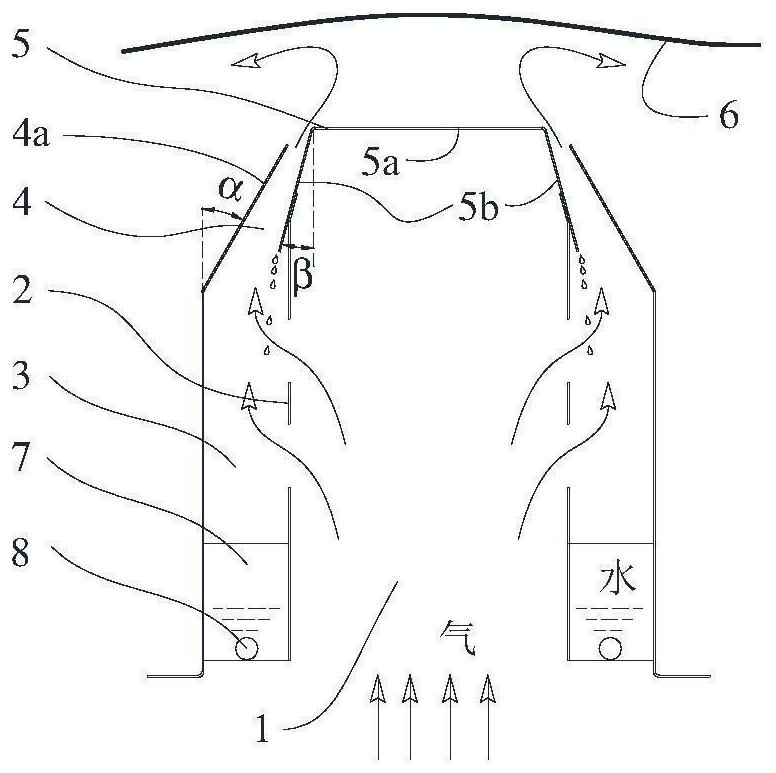
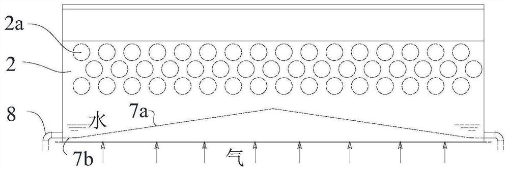
[0028] Such as figure 1 As shown, a gas-liquid quenching nozzle structure of a hovering furnace includes an air inlet chamber 1, a nozzle 4, a waterproof cover 5, a gas-liquid separation chamber 3, and a drainage groove 7 arranged at the bottom of the gas-liquid separation chamber. The air inlet chamber 1 and the gas-liquid separation chamber 3 are separated by a circular orifice plate 2, and the holes of the orifice plate are as follows: image 3 shown. The top of the orifice plate 2 is connected and fixed to the inner side of the waterproof cover water eaves 5b, and the lower end of the waterproof cover water eaves 5b protrudes a certain distance to facilitate the drop of liquid droplets into the gas-liquid separation chamber 3. The air first enters the air intake chamber 1, and flows into the nozzle 4 through the orifice plate 2 in turn. The design size of the nozzle 4 is relatively narrow, and the design flow velocity is about 40m / s. The gas forms an air cushion layer be...

Embodiment 2

[0033] Embodiment two is similar to embodiment one, the difference is:

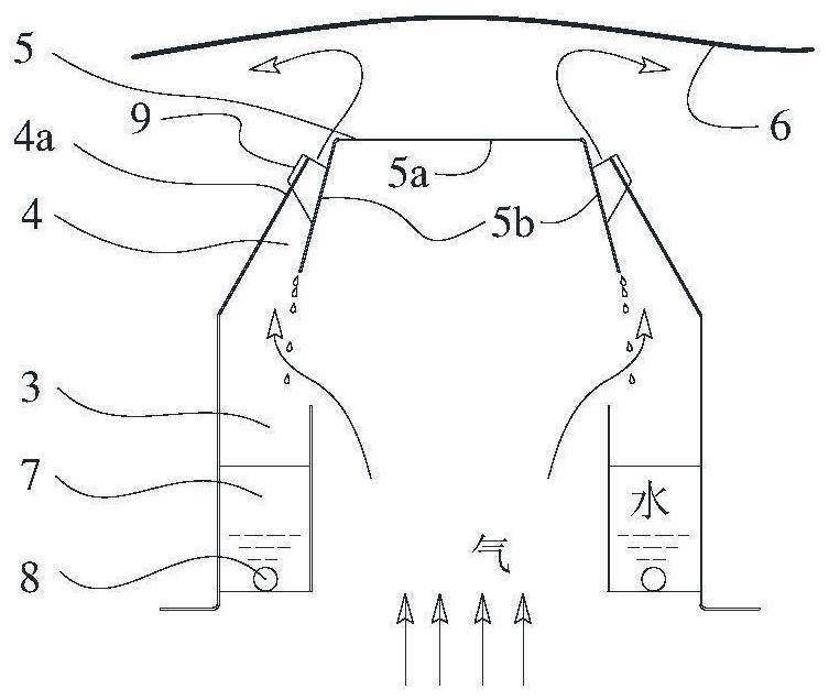
[0034] Such as figure 2 As shown, there is no obvious separation boundary between the air inlet chamber 1 and the gas-liquid separation chamber 3, and the orifice plate is cancelled. The outer side of the water eaves 5b of the waterproof cover is fixed on the spout bending plate 4a through the rib plate 9. Its advantage is that it can reduce part of the loss of air circulation resistance and reduce the height of the nozzle.

Embodiment 3

[0036] Embodiment three is similar to embodiment one, the difference is:

[0037] Such as Figure 4 As shown, the drainage groove 7 is a one-sided diversion method, and the bottom plate is in the form of a flat plate composed of an inclined section bottom plate 7a and a horizontal section bottom plate 7b, and the slope of the inclined section bottom plate 7a is 0.04.


PUM


Abstract

The invention belongs to the field of metal heat treatment, and discloses an air cushion furnace gas-liquid quenching spray nozzle structure and a gas-liquid cooperative quenching system. An air floating spray nozzle adopted at present generally only considers the circulation of single-phase gas, and is mainly suitable for a gas quenching area, while the water quantity in a water mist area is large, if the traditional gas quenching spray nozzle is still adopted, the risk that the water mist flows into an air duct along a lower-layer gas nozzle can be caused, after long-term operation, water isprone to accumulating in the air duct so as to accelerate structural corrosion, and if the water accumulation amount is large and the arrangement position of a fan is low, the possibility of water flowing into the fan is further achieved so as to threaten the safety operation of the system. The air cushion furnace gas-liquid quenching spray nozzle structure is improved, and comprises an air inletchamber, a nozzle, and a waterproof cover, a gas-liquid separation cavity and a drainage groove formed in the bottom of the gas-liquid separation cavity different from the traditional air floating spray nozzle, gas circulation can be guaranteed, so that the float of an aluminum plate is achieved, and liquid evaporation cooling is accelerated; and accumulated water can be effectively discharged, so that the operation risk of the gas quenching system is reduced.

Description

technical field [0001] The invention belongs to the field of metal heat treatment, and in particular relates to a gas-liquid quenching nozzle structure of an air cushion furnace and a gas-liquid synergistic quenching system. Background technique [0002] The continuous air cushion furnace can be used for heating and quenching treatment of aluminum alloy strips, and the aluminum alloy strips after heat treatment are widely used in aerospace and automobile manufacturing and other fields. In order to meet the high standards of material hardness, strength, toughness and fatigue strength required by the manufacturing industry in different fields, the aluminum strip quenching process needs to adopt different cooling control processes, usually including water quenching, gas quenching, and water-gas partitioning. [0003] The traditional water quenching process is a separate partition, and the high-pressure and high-speed water mist impacts the hot aluminum plate to achieve rapid co...

Claims


Application Information

Patent Timeline
IPC IPC(8): C21D1/667C21D9/573C21D9/63C22F1/04
CPCC21D1/667C21D9/63C21D9/573C22F1/04
Inventor 高玉峰龚奇龙秦明臣高如超徐昭然
Owner BEIJING AVIATION FEIFANG MACHINERY EQUIP FACTORY
Why Eureka
Try Eureka