
Fan impeller and fan

A fan impeller and impeller technology, applied in the direction of machines/engines, wind power generation, mechanical equipment, etc., can solve the problems of insufficient precision of numerical control equipment, uneven material hardness, increased fan leakage, etc., to avoid turning or residual width Effects of inconsistency, reduced airflow pulsation, improved fan noise

Active Publication Date: 2020-10-27
山东章晃机械工业有限公司
View PDF4 Cites 0 Cited by
  • Summary
  • Abstract
  • Description
  • Claims
  • Application Information

AI Technical Summary

Problems solved by technology

[0004] Although the theoretical design of each blade of the impeller is identical, in the process of impeller machining, when the outer circle of the impeller is finally turned, due to the lack of precision of the numerical control equipment and the uneven hardness of the material, the blade peaks in the length direction of the impeller remain. The width of the blade varies, and if the deviation is large, the top of the blade peak will not be turned in the direction of the entire length of the impeller, resulting in increased fan leakage and flow exceeding the design standard tolerance; at the same time, increased air flow pulsation and high noise

Method used


Image

  • Fan impeller and fan
  • Fan impeller and fan
  • Fan impeller and fan

Examples


Embodiment Construction

[0028] In order to explain the overall concept of the present application more clearly, the following detailed description will be given by way of examples in combination with the accompanying drawings.

[0029] In the following description, many specific details are set forth in order to fully understand the application, but the application can also be implemented in other ways different from those described here, therefore, the protection scope of the application is not limited by the specific details disclosed below. EXAMPLE LIMITATIONS.

[0030] In addition, in the description of the present application, it should be understood that the terms "top", "bottom", "inner", "outer", "axial", "radial", "circumferential" and the like indicate directions or The positional relationship is based on the orientation or positional relationship shown in the drawings, which is only for the convenience of describing the application and simplifying the description, and does not indicate or ...


PUM


Abstract

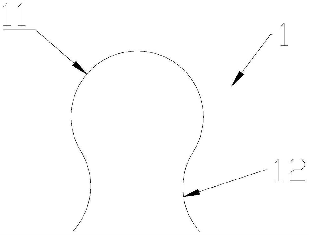
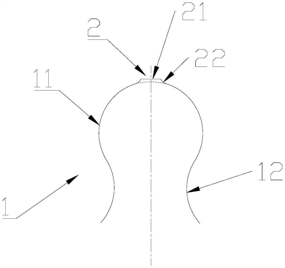
The invention discloses a fan impeller. The fan impeller comprises a plurality of blade teeth, wherein each blade tooth is provided with a blade peak part; the outer surface of each blade peak part isan arc surface; a wide rib protruding out of each blade peak part is arranged at the top end of each blade tooth; the distance from the top end of each wide rib to the center of the impeller is equalto the radius of the impeller; and each wide rib enables the blade top to have a large machinable area, can allow / adapt to a large error rate of a numerical control lathe, and facilitates the subsequent reprocessing process, so that the impeller with the distance from the top end to the center of the impeller being equal to the radius of the impeller can be obtained through accurate processing,and the problem of deviation from theoretical design to the product forming process is solved. The invention further provides a fan. The fan comprises a casing and the impeller arranged in the casingand matched with the casing, wherein the impeller is the fan impeller. The fan is convenient to process and manufacture, the impeller and the casing are well sealed, the leakage rate is low, the fan noise is low, the operation is stable, the stability and the wear resistance are high, and the service life is long.

Description

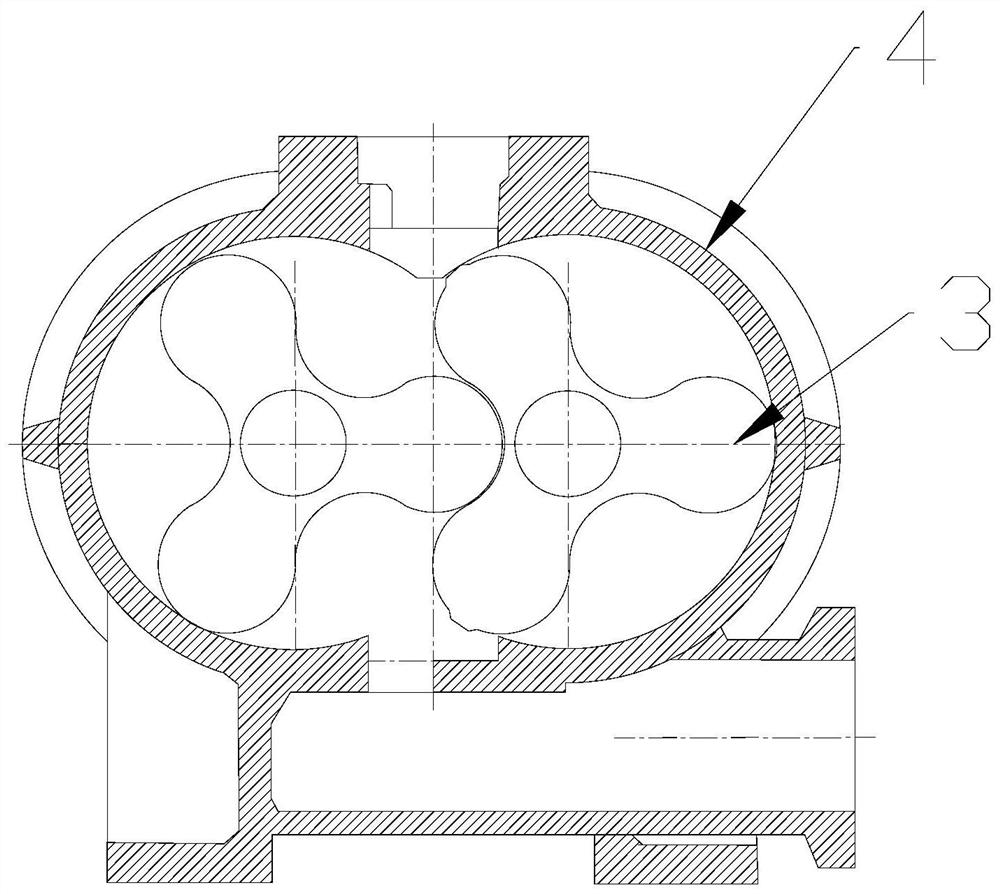
technical field [0001] The present application relates to the technical field of Roots blower, in particular to a fan impeller and a fan. Background technique [0002] The Roots blower is a volumetric blower, which utilizes the relative movement of the rotor to realize gas delivery or compression. It is widely used because of its simple structure and convenient manufacture. The Roots blower generally includes several parts such as the casing and the impeller inside the casing. The impeller as a rotating part is the key component of the Roots blower. The precision of the impeller has a great influence on the performance of the fan. [0003] Usually the Roots blower has two matching impellers, and the impellers rotate relatively in the casing, such as figure 2 As shown, since each impeller adopts the envelope of circular arc, involute or epicycloid, the blade teeth of each impeller are exactly the same, and the two impellers are also exactly the same, which greatly reduces th...

Claims


Application Information

Patent Timeline
IPC IPC(8): F04C18/12F04C29/00F04C29/06
CPCF04C18/126F04C18/084F04C29/06Y02E10/72
Inventor 韩春玉仇学莲管凯张磊
Owner 山东章晃机械工业有限公司
Learn More