Optical time-domain reflectometer system and measuring and using method thereof

A technology of optical time domain reflectometer and light source, applied in transmission system, electromagnetic wave transmission system, electromagnetic receiver, etc., can solve the problem that OTDR resolution and dynamic range cannot be improved at the same time

Inactive Publication Date: 2016-08-17
INST OF SEMICONDUCTORS - CHINESE ACAD OF SCI
View PDF5 Cites 11 Cited by
  • Summary
  • Abstract
  • Description
  • Claims
  • Application Information

AI Technical Summary

Problems solved by technology

[0004] In order to solve the above problems, the main purpose of the present invention is to provide an optical time domain reflectometer with high resolution, large dynamic range a

Method used


Image

  • Optical time-domain reflectometer system and measuring and using method thereof
  • Optical time-domain reflectometer system and measuring and using method thereof
  • Optical time-domain reflectometer system and measuring and using method thereof

Examples


Embodiment Construction

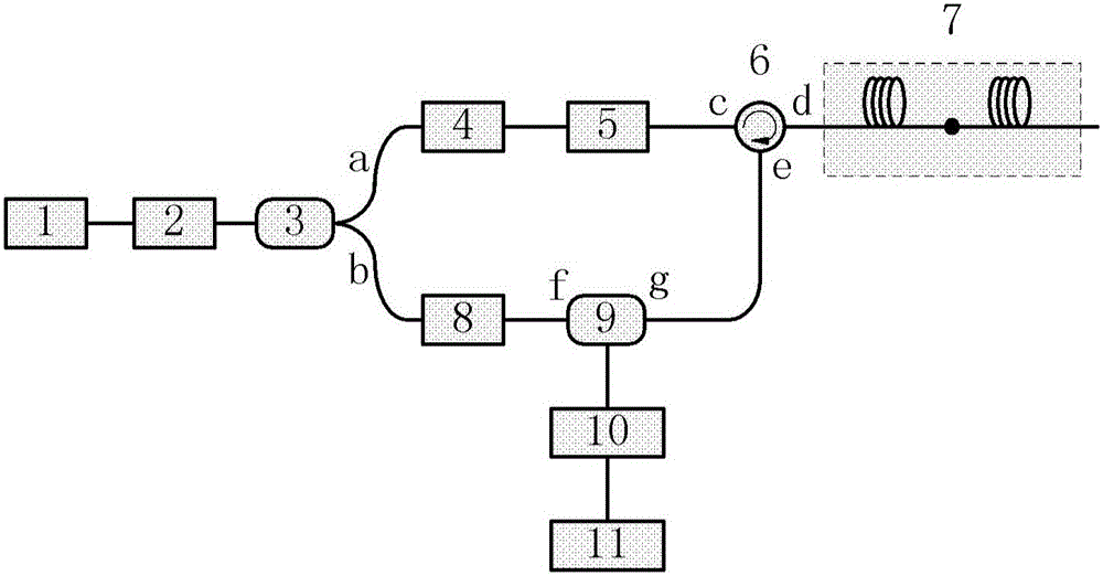
[0023] figure 1 The device structure diagram of the novel optical time domain reflectometer proposed by the present invention is shown. Such as figure 1 As shown, the device includes:

[0024] A narrow linewidth laser 1, which is used to provide a seed light source;

[0025] The optical fiber amplifier 2 is used to amplify the optical power of the seed light source; the light source can be a semiconductor DFB laser with a narrow linewidth, a DBR laser or a fiber laser.

[0026] Fiber coupler 3, which is used to divide the amplified seed light source into two outputs a and b;

[0027] An optical wavelength encoder 4, which is used to modulate the output light of the seed light source a path to generate signal light pulses;

[0028] Optical isolator 5, which is used to unidirectionally collimate the optical pulse signal of the a output end of fiber coupler 4 to the c input end of optical circulator 6; this optical isolator can be a fiber collimator, and the optical fiber rin...


PUM


Abstract

The invention provides an optical time domain reflectometer system with high resolution, large dynamic range and simple structure and its measurement method, which includes a narrow linewidth laser, an optical fiber amplifier, an optical fiber coupler, an optical wavelength encoder, an optical isolator, Optical fiber coupler optical circulator, optical fiber link under test, optical wavelength encoder, optical coupler, photodetector and signal detection device. The invention is used to solve the problem that the traditional OTDR resolution and dynamic range cannot be improved simultaneously.

Description

technical field [0001] The invention belongs to the technical field of optical fiber link testing, and more specifically relates to an optical time domain reflectometer system and a measuring and using method of a modulation format wavelength code. Background technique [0002] The optical time domain reflectometer (OTDR) is an instrument for understanding the uniformity, defect, fracture, joint coupling and other properties of the optical fiber through the analysis of the measurement curve. It is made according to the principle of light backscattering and Fresnel inversion, and uses the backscattering light generated when light propagates in the optical fiber to obtain attenuation information, which can be used to measure fiber attenuation, joint loss, fiber fault location and understand The loss distribution of optical fiber along the length, etc., is an indispensable tool in the construction, maintenance and monitoring of optical cable. It is made according to the princi...

Claims


Application Information

Patent Timeline
IPC IPC(8): H04B10/071H04B10/524H04B10/564H04B10/61H04B10/69
CPCH04B10/071H04B10/524H04B10/564H04B10/615H04B10/691
Inventor 祝宁华孙文惠王玮钰刘建国陈伟
Owner INST OF SEMICONDUCTORS - CHINESE ACAD OF SCI
Why Eureka
Try Eureka