Control valve for gas stove and gas stove

A technology for controlling valves and gas stoves, which is applied to household stoves/stoves, applications, valve devices, etc., can solve the problems of incoordination of knob switches, ignition failure, ignition failure, etc., and achieves simple and compact structure, reliable operation and high precision. high effect

Pending Publication Date: 2020-10-27
VATTI CORP LTD
View PDF0 Cites 0 Cited by
  • Summary
  • Abstract
  • Description
  • Claims
  • Application Information

AI Technical Summary

Problems solved by technology

[0003] The purpose of the present invention is to provide a control valve for a gas cooker, which solves the problem of inconsistency between pre-ignition and delayed ign

Method used


Image

  • Control valve for gas stove and gas stove
  • Control valve for gas stove and gas stove
  • Control valve for gas stove and gas stove

Examples


Embodiment Construction

[0021] In order to make the object, technical solution and advantages of the present invention clearer, the present invention will be further described in detail below in conjunction with the accompanying drawings and embodiments. It should be understood that the specific embodiments described here are only used to explain the present invention, not to limit the present invention.

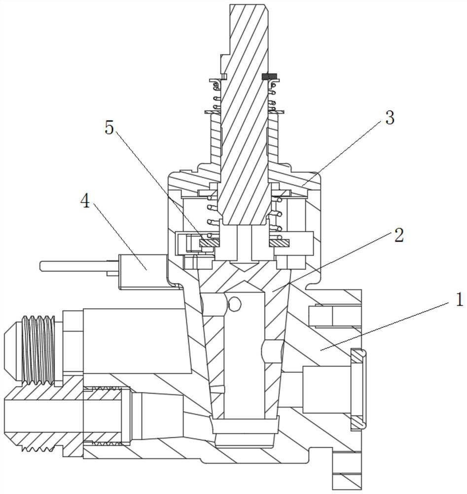
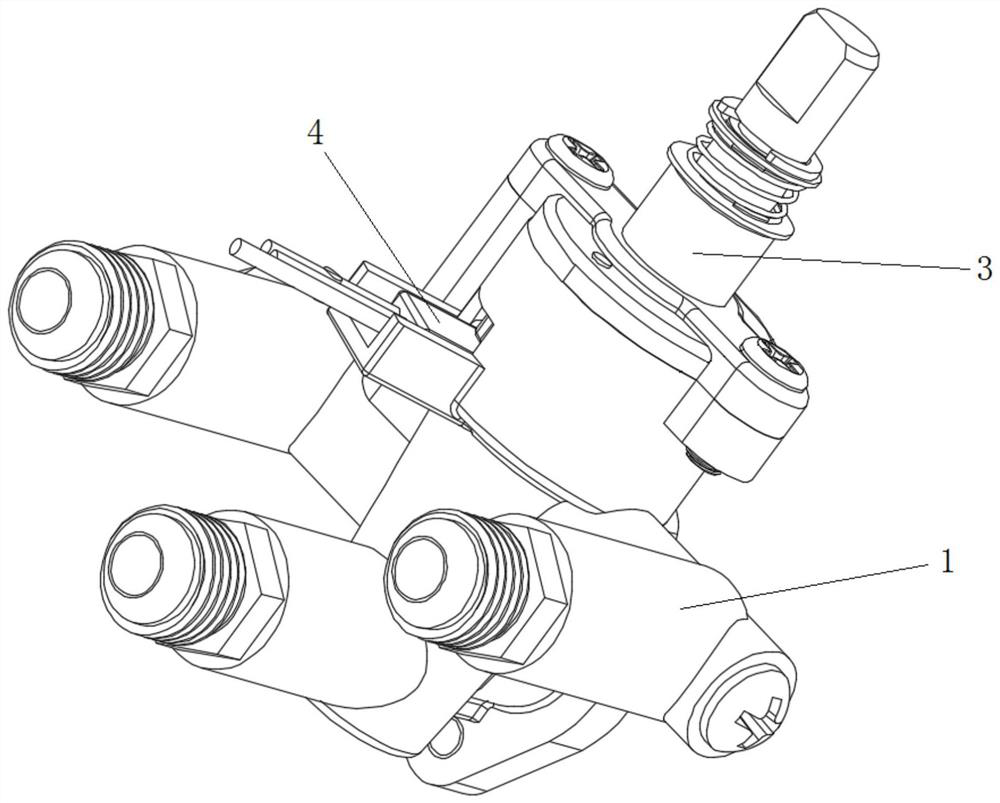
[0022] Embodiment 1 of the present invention provides a control valve for a gas cooker, such as figure 1 , figure 2 and Figure 5 As shown, it includes a valve housing 1, a valve core 2, a valve cover assembly 3, a Hall element 4 and a control assembly 5. The valve housing 1 has a hollow inner cavity, and the valve core 2 is arranged in the inner cavity of the valve housing 1. , the bonnet assembly 3 is arranged above the valve core 2 and fixedly connected to the valve housing 1, the control assembly 5 is arranged between the valve core 2 and the bonnet assembly 3, and the side wall of the valve...


PUM


Abstract

The invention discloses a control valve for a gas stove. The control valve comprises a valve shell, a valve element, a valve cover assembly, a Hall element and a control assembly. The valve element isarranged in the valve shell. The valve cover assembly is arranged above the valve element and fixedly connected with the valve shell. The control assembly is arranged between the valve element and the valve cover assembly. A through groove is formed in the side wall of the valve shell. The Hall element is arranged in the through groove and connected with the control assembly in a matched manner.When the control valve is used, the control assembly is arranged between the valve element and the valve cover assembly, the Hall element matched with the control assembly is arranged on the valve shell, and the problems that in the ignition process, advance ignition, delayed ignition and the like are prone to being not coordinated with a rotary switch, and consequently ignition failures or non-ignition or deflagration happens are effectively solved. The control valve is simple and compact in structure, small in size, high in precision, reliable in work, simple in process, low in cost, free ofmaintenance, long in service life, environmental-friendly and capable of saving energy.

Description

technical field [0001] The invention belongs to the technical field of kitchen appliances, and in particular relates to a control valve for a gas stove and the gas stove. Background technique [0002] The control valve of the gas cooker is the main structural part of the gas cooker. At present, the household gas cooker in the market generally uses a plug valve to control the opening and closing of the cooker and the adjustment of the firepower. The plug valve usually includes a valve body, a valve core, a valve shaft, and a valve cover. And micro switch, etc.; the working process is as follows: press down the valve shaft (that is, the rotating shaft) to rotate, and the rotating shaft drives the fixed plate, paddle and valve core to rotate, the fixed plate plays the role of initial positioning and child lock, and the paddle controls the ignition of the igniter The role of the micro switch is to toggle the shrapnel of the micro switch to open / close the micro switch, and the op...

Claims


Application Information

Patent Timeline
IPC IPC(8): F16K5/08F16K5/02F24C3/12
CPCF16K5/02F16K5/08F24C3/126
Inventor 罗长兵罗峰陈琦刘凯潘叶江
Owner VATTI CORP LTD
Why Eureka
Try Eureka