Valve position indicator and valve position indicating system

A technology of indicators and valves, applied in the direction of valve devices, valve details, valve shell structures, etc., can solve the problem of outputting wrong signals when valves are open and closed

Active Publication Date: 2020-10-27
NUCLEAR POWER INSTITUTE OF CHINA
View PDF15 Cites 1 Cited by
  • Summary
  • Abstract
  • Description
  • Claims
  • Application Information

AI Technical Summary

Problems solved by technology

[0009] 3. The valve position indicator itself is a safety device, and it is not allowed to output wrong signals for

Method used


Image

  • Valve position indicator and valve position indicating system
  • Valve position indicator and valve position indicating system
  • Valve position indicator and valve position indicating system

Examples


Embodiment 1

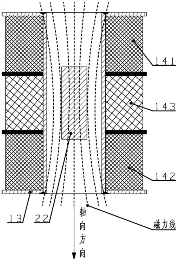
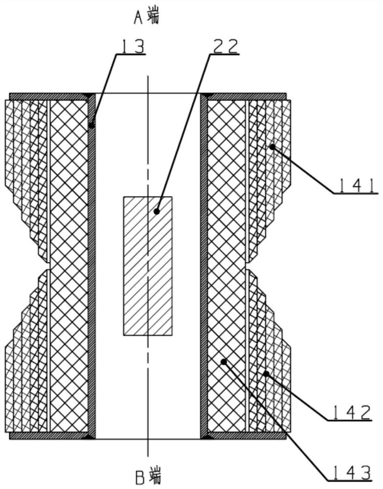
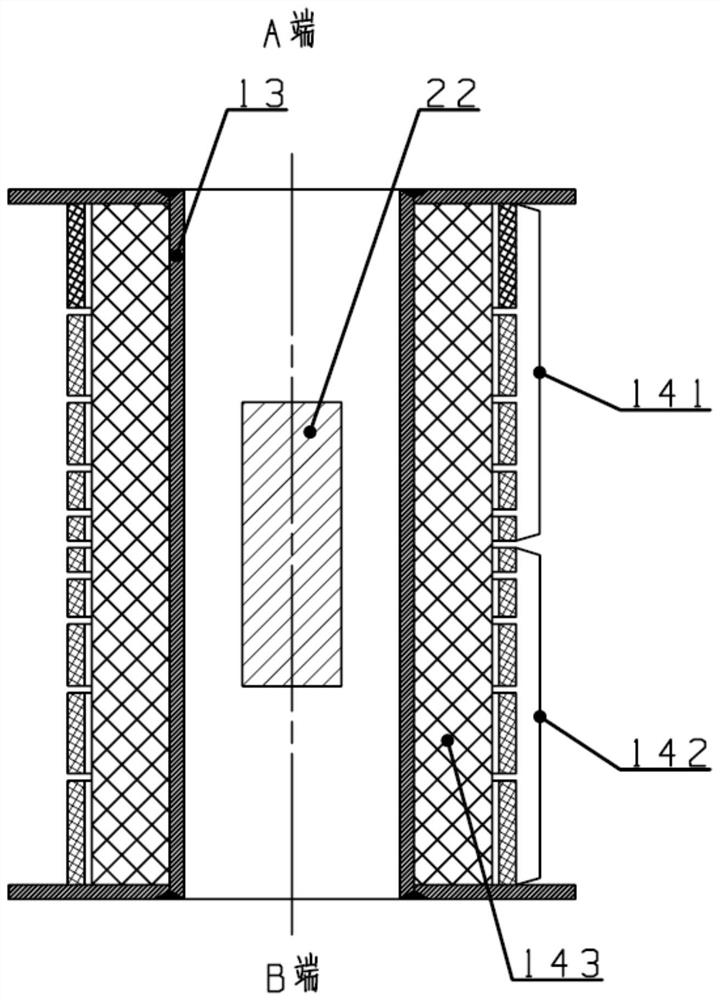
[0066] The valve position indicator includes the body structure of the valve position indicator 1, the body structure includes a continuous valve position signal sensing part, the continuous valve position signal sensing part includes a skeleton 13, a coil 14, and the coil 14 includes a primary coil 143 1. Secondary coil, it is characterized in that, described primary coil 143 is wound outside skeleton 13, and the quantity of described secondary coil is 2, and 2 secondary coils are wound on primary coil 143 simultaneously, wherein one secondary The number of turns of the coil increases along the midpoint of the axis of the skeleton 13 toward the end A of the skeleton 13 , and the number of turns of the other secondary coil increases along the midpoint of the axis of the skeleton 13 toward the end B of the skeleton 13 .

[0067] The above-mentioned technical solution can achieve the purpose of improving the measurement range and the strength of the measurement signal, thereby im...

Embodiment 2

[0107] A valve position indicating system,

[0108] like Image 6 As shown, it includes the above-mentioned valve position indicator 1 and cabinet 6. The cabinet 6 introduces the continuous valve position signal output by the continuous valve position signal sensing part from the valve position indicator 1 and the output signal of two magnetic control switch probes. Limit signal; the limit signals of the switching value output by the two magnetically controlled switch probes are the upper limit signal and the lower limit signal respectively, and the upper limit signal and the lower limit signal respectively represent the upper limit position and the lower limit position of the valve;

[0109] The continuous valve position signal is an analog signal, the upper limit signal and the lower limit signal respectively represent the standard current signal of 4mA and 20mA;

[0110]Cabinet 6 is equipped with a self-test early warning program: if the current continuous valve position s...


PUM


Abstract

The invention discloses a valve position indicator and a valve position indicating system. A body structure of the valve position indicator is included. The body structure comprises a continuous valveposition signal induction part which comprises a framework and a coil. The coil comprises a primary coil and two secondary coils. The coil is characterized in that the primary coil winds the framework externally, the two secondary coils wind the primary coil at the same time, the number of windings of one of the secondary coils is increased from a center of axis of the framework to a terminal A direction of the framework, and the number of windings of the other secondary coil is increased from the center of axis of the framework to a terminal B direction of the framework. By adopting a compensating coil structure, an induced electromotive force is increased, a nonlinear section is improved, and the linear measuring range of a continuous valve position signal is enlarged.

Description

technical field [0001] The invention relates to the field of valve position measurement, in particular to a valve position indicator and a valve position indicating system. Background technique [0002] The invention relates to a valve position indicator, in particular to a valve core linear position indicator with multiple functions applied to valves in important parts of nuclear power plants. The valve position indicator can control Under the conditions of high temperature, high pressure and strong radiation, any opening height of the working valve can be measured and fault alarmed. [0003] The valve position indicator is used to indicate the switch status or opening height (ie opening degree) of the valve, which is beneficial to the on-site display of the valve position or the real-time transmission of the valve position signal. At present, the principles used in valve position indicators mainly include limit switch type, reed switch type, potentiometer type, strain typ...

Claims


Application Information

Patent Timeline
IPC IPC(8): F16K37/00F16K27/00
CPCF16K37/0033F16K37/0041F16K27/00
Inventor 罗世洪王宇翔郭松李朋洲袁晟毅张冬林秦胜杰李晓钟
Owner NUCLEAR POWER INSTITUTE OF CHINA
Why Eureka
Try Eureka