High-contrast nanosecond pulse laser waveform measuring device and measuring method

A technology of pulsed laser and waveform measurement, applied in the direction of instruments, etc., can solve the problems of limitation, large linear measurement range, inaccessibility, etc., achieve high power, achieve power, and avoid damage

Pending Publication Date: 2022-03-01
LASER FUSION RES CENT CHINA ACAD OF ENG PHYSICS
View PDF3 Cites 0 Cited by
  • Summary
  • Abstract
  • Description
  • Claims
  • Application Information

AI Technical Summary

Problems solved by technology

Although this method only needs to be equipped with an extremely low-voltage DC power supply, it has a certain protective effect on expensive measuring equipment such as oscilloscopes. Compared with vacuum phototubes, semiconductor photodetectors can have faster response and are more suitable for hundreds of picosecond pulses. Waveform measurement, but semiconductor photodetectors usually have a small linear dynamic range in this method. Compared with the first method, a larger linear measurement range cannot be obtained after data splicing
Therefore, the above two nanosecond pulse waveform measurement methods are limited in the face of high-contrast shaped pulse measurement output by high-power laser devices

Method used


Image

  • High-contrast nanosecond pulse laser waveform measuring device and measuring method

Examples


Embodiment 1

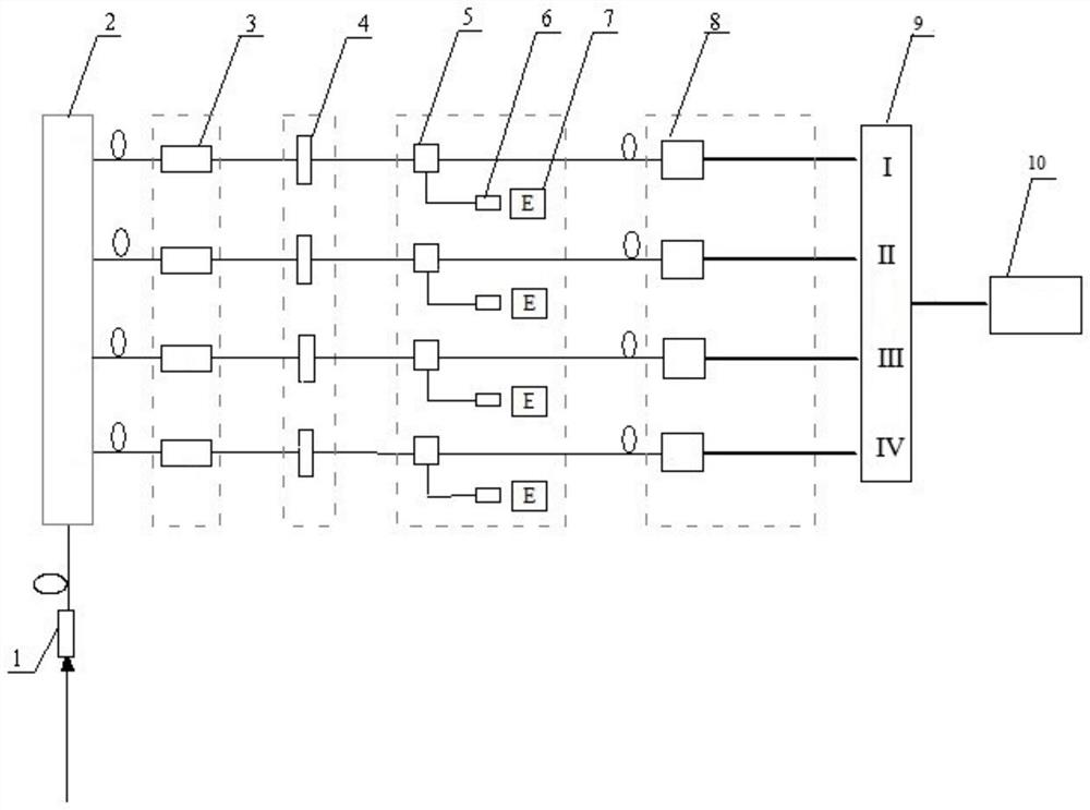
[0064] In this embodiment, the type of semiconductor photodetector 8 is: DSC50S, bandwidth: 12Ghz, response spectrum range: 1000-1650nm, response sensitivity (1053nm): 0.6A / W, output impedance: 50Ω, linear dynamic range: 0- 1.5V; the bandwidth parameters of the connecting cable between the oscilloscope and the computer are: 18G, impedance: 50Ω; the parameters of the oscilloscope 9 are: bandwidth 8G, input impedance: 50Ω; the model of the energy meter 7 is: PD10-Pj-C.

[0065] The focal length of fiber coupler 1 and fiber collimator 6 is f=36.5mm, aperture φ=10mm, and the fiber is 1053nm single-mode fiber; fiber beam splitter I2: channel fiber interface FC / PC, output 4 channels, and the splitting ratio is 1:1:1:1; fiber optic beam splitter II5: channel fiber optic interface FC / PC, output 2 channels, splitting ratio (waveform channel: energy meter channel) is 1:10; fiber optic pulse duplicator 4: number of pulse duplication 4, pulse bottom interval 40ns; adjustable optical fiber...


PUM

PropertyMeasurementUnit
impedanceaaaaaaaaaa

Abstract

The invention discloses a high-contrast nanosecond pulse laser waveform measuring device. The device comprises an optical fiber coupler, an optical fiber beam splitter I, an adjustable optical fiber attenuator, an optical fiber pulse duplicator, an optical fiber beam splitter II, an optical fiber collimator, an energy meter, a semiconductor photoelectric detector, an oscilloscope and a computer. The optical fiber beam splitter I is connected with the optical fiber coupler, and the optical fiber beam splitter I divides laser to be measured into four beams with equal energy. According to the device disclosed by the invention, the waveform data of different truncation parts of the laser waveform can be obtained, and finally, the data are averaged and spliced to obtain the high-contrast nanosecond pulse laser waveform. The laser waveform measuring device disclosed by the invention can realize measurement of high-power and high-contrast nanosecond pulse laser waveforms, and is particularly suitable for precise measurement of complex nanosecond pulse time waveforms of large-scale high-power laser devices.

Description

technical field [0001] The invention belongs to the technical field of high-power laser parameter measurement, and in particular relates to a high-contrast nanosecond pulse laser waveform measurement device and measurement method. Background technique [0002] The output pulsed laser energy of large-scale high-power laser devices can reach the order of 10,000 joules. The most common pulsed laser waveform is a multi-step shaped pulse waveform with high contrast. The contrast between the pulse main peak and the pulse front step of this pulse waveform is as high as Hundreds to one, and the pulse waveform has a complex pulse waveform profile and fast rise time. In order to provide accurate pulse waveform parameters for physical experiments, real-time measurement of high-contrast shaped pulse waveforms output by large laser devices is required. [0003] At present, there are mainly the following methods for waveform measurement of high-contrast nanosecond pulses output by large-...

Claims


Application Information

Patent Timeline
Patent Type & Authority Applications(China)
IPC IPC(8): G01J11/00
CPCG01J11/00
Inventor 董军夏彦文卢宗贵刘华张波曾发孙志红
Owner LASER FUSION RES CENT CHINA ACAD OF ENG PHYSICS
Why Eureka
Try Eureka