
Shaft furnace air guide wall water beam structure and applying method thereof

An application method and a technology of an air guide wall, which are applied in the field of metallurgical pelletizing shaft furnaces, can solve the problem of uneven distribution of cooling wind direction of the water beam of the air guide wall, insufficient wear resistance of the water beam of the air guide wall, and cooling of the water beam of the air guide wall. Insufficient effects, etc.

Pending Publication Date: 2020-10-27
MAANSHAN IRON & STEEL CO LTD
View PDF0 Cites 0 Cited by
  • Summary
  • Abstract
  • Description
  • Claims
  • Application Information

AI Technical Summary

Problems solved by technology

[0005] 1) The cooling effect of the water beam on the wind guide wall is insufficient;
[0006] 2) The wear resistance of the water beam of the wind guide wall is not enough;
[0007] 3) The cooling wind direction of the water beam of the wind guide wall is unevenly distributed

Method used


Image

  • Shaft furnace air guide wall water beam structure and applying method thereof
  • Shaft furnace air guide wall water beam structure and applying method thereof
  • Shaft furnace air guide wall water beam structure and applying method thereof

Examples


Embodiment Construction

[0031] In the present invention, it should be understood that the terms "length", "width", "upper", "lower", "front", "rear", "left", "right", "vertical", "horizontal" ", "Top", "Bottom", "Inner", "Outer", "Clockwise", "Counterclockwise", "Axial", "Plane Direction", "Circumferential" and other indications are based on The orientation or positional relationship shown in the drawings is only for the convenience of describing the present invention and simplifying the description, and does not indicate or imply that the referred device or element must have a specific orientation, be constructed and operated in a specific orientation, and therefore cannot be understood as Limitations on the Invention.

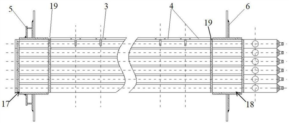
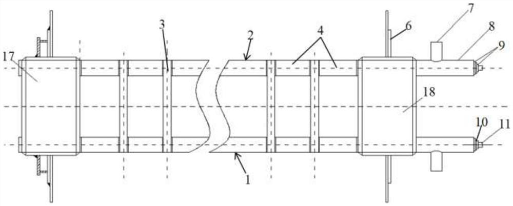
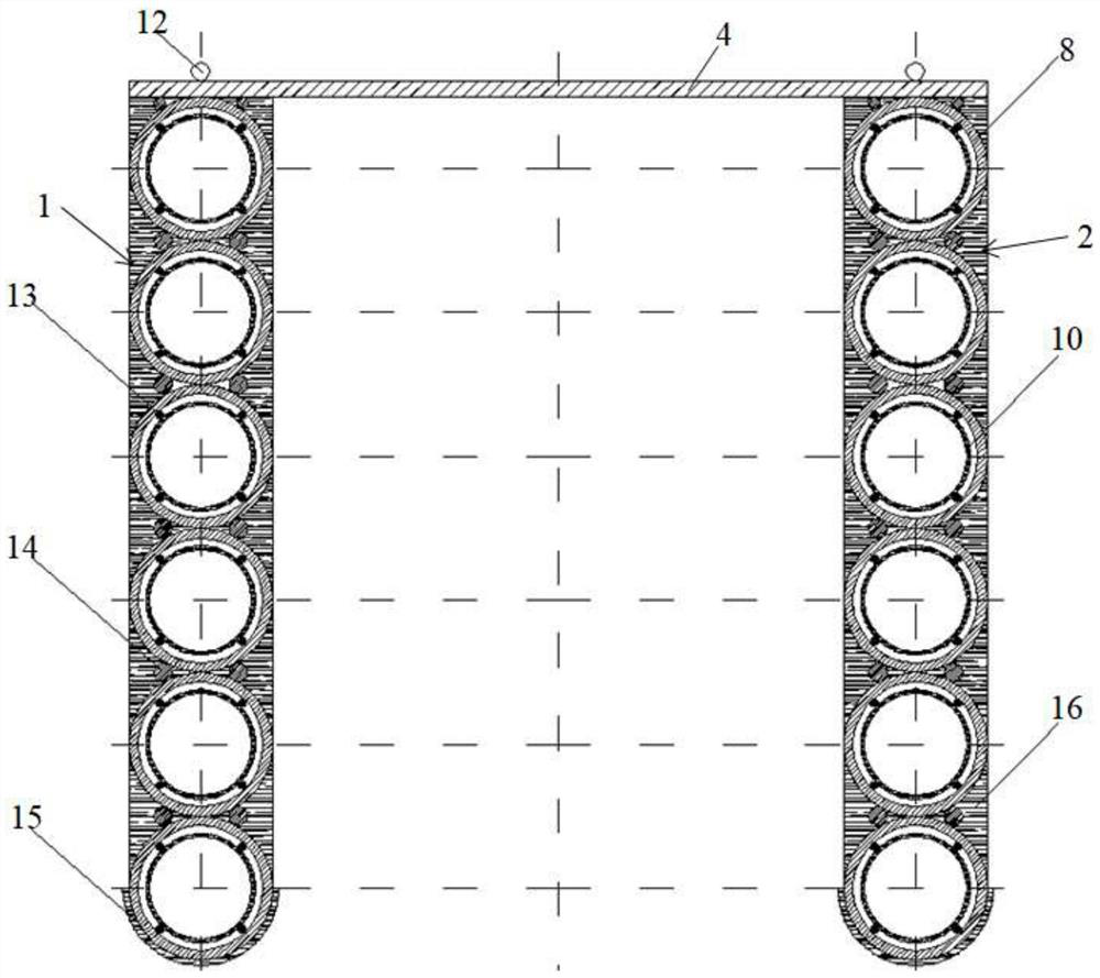
[0032] Such as Figure 1 to Figure 3 As shown, a water beam structure for the wind guide wall of a shaft furnace is characterized in that it includes water beam I1, water beam II2 and a support mechanism for supporting the wind guide wall, one end of the support mechanism is connec...


PUM


Abstract

The invention discloses a shaft furnace air guide wall water beam structure. The shaft furnace air guide wall water beam structure comprises a water beam I, a water beam II and a supporting mechanismused for supporting an air guide wall, wherein one end of the supporting mechanism is connected with the water beam I, the other end of the supporting mechanism is connected with the water beam II, the water beam I and the water beam II each comprise a plurality of water pipes, the water pipes are of double-layer concentric structures, the water pipes comprise water inlet pipes and water return pipes, the water return pipes are nested in the water inlet pipes, water inlets of the water inlet pipes and water return openings of the water return pipes are located on the same sides of the water pipes, and circulating cooling water enters the water inlet pipes from the water inlets, flows to the tail ends of the water inlet pipes to enter the middle sleeve water return pipes, then returns to the water return openings of the water inlet ends and flows out to a water return tank system. Thus, the cooling effect of the water beam pipeline is improved, the pipes are distributed in an uniform heating mode, and then the service life is prolonged; and online maintenance can be conveniently carried out under the condition of no suspend production after water leakage occurs to pipeline through holes, the water return pipes in the middles of the water inlet pipes are drawn out, pipes are sleeved in the water inlet pipes again, the pipes sleeved in the water inlet pipes again are through pipes, water enters one ends from the through pipes, and the water returns from the other ends of the through pipes.

Description

technical field [0001] The invention belongs to the technical field of metallurgical pellet shaft furnaces, and in particular relates to a water beam structure of an air guide wall of a shaft furnace and an application method thereof. Background technique [0002] At present, the vast majority of domestic pelletizing shaft furnaces adopt the structural form of the combination of air guide wall water beam, air guide wall and drying bed. However, the large water beam is generally butt-welded with Ф159×20㎜ seamless steel pipes; the air guide wall water beam is one of the core equipment of the pelletizing shaft furnace, and the working environment in the furnace is relatively harsh. The load-bearing wind guide wall must also bear the scour of high-speed high-temperature cooling wind mixed with dust. Since more than 70% of the cooling air will reach the drying bed through the inner hole of the air guide wall to dry the raw pellets, the cooling air will change the flow direction ...

Claims


Application Information

Patent Timeline
IPC IPC(8): F27B1/24
CPCF27B1/24
Inventor 陈云孟令国刘晓超胡彤曹兵吴立奇张学钢杨征曹悦欣
Owner MAANSHAN IRON & STEEL CO LTD
Learn More