
Structure and method for improving MIMO system antenna isolation

An antenna isolation and antenna technology, applied in antennas, antenna coupling, antenna components, etc., can solve the problems that the antenna occupies a large space, is not a system design idea, and its efficiency and coverage are not as good as vertically polarized antennas.

Pending Publication Date: 2020-10-27
YANGO UNIV
View PDF0 Cites 0 Cited by
  • Summary
  • Abstract
  • Description
  • Claims
  • Application Information

AI Technical Summary

Problems solved by technology

At present, the distance between the antennas of most indoor base station products can still be greater than the near-field radiation of the omnidirectional antenna. In this case, in order to improve the isolation of the antenna, the general design is to use cross-polarization by design. The former is very effective in improving the isolation, but the efficiency and coverage of the horizontally polarized antenna are not as good as the vertically polarized antenna, and the horizontally polarized antenna needs to occupy a large area in the low frequency band. Space is a compromise consideration. The latter is to find the zero point of antenna radiation and align the zero point position with adjacent antennas to improve the isolation between antennas. However, this method is not suitable for antennas with good omnidirectional radiation, and Because there is often more than one adjacent antenna, it is often difficult to take care of both. For this reason, this method has a large blindness and is not a system design idea.

Method used


Image

  • Structure and method for improving MIMO system antenna isolation
  • Structure and method for improving MIMO system antenna isolation
  • Structure and method for improving MIMO system antenna isolation

Examples


Embodiment Construction

[0028] In order to make the features and advantages of this patent more obvious and easy to understand, the following special examples are described in detail as follows:

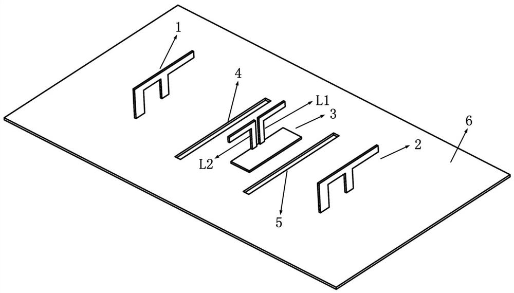
[0029] Such as figure 1 As shown, the structure that can improve the antenna isolation of MIMO system provided by this embodiment includes an isolation unit 3 for affecting the antenna radiation electromagnetic field and two etching grooves on both sides of the isolation unit 3 (including the first isolation groove 4 and the second isolation tank 5). Among them, the isolation unit 3 adopts a double-arm inverted L-shaped structure (such as figure 1 the L-arms of L1 and L2).

[0030] In this embodiment, the total length of the L arms is about 1 / 4 of the working wavelength of the antenna. The lengths of the two L arms can be slightly different. By adjusting the lengths of the two arms, the isolation and the corresponding bandwidth can be adjusted. Generally, the preferred total The length can be 1 / 4 of the ...


PUM


Abstract

The invention provides a structure and a method for improving MIMO system antenna isolation. The structure comprises an isolation unit and two etching grooves, wherein the isolation unit is arranged on a metal antenna bottom plate and located between two antennas, and the distance between the two antennas is larger than half of the working wavelength of the antennas; the two etching grooves are located in the two sides of the isolation unit; and the isolation unit is of a double-arm inverted-L-shaped structure composed of two L-shaped arms. The structure and the method can be applied to improvement of the isolation degree of the existing indoor and outdoor small base station omnidirectional antenna, have the replicability and are simple and rapid in design, the isolation is obviously improved, and compared with neutral line decoupling and resonator decoupling, additional matching design does not need to be carried out on an input port, the design flexibility is higher, and compared with metamaterial decoupling, the design is simpler, the cost is lower, and the structural compatibility is higher.

Description

technical field [0001] The invention belongs to the technical field of wireless communication, and in particular relates to a structure and a method for improving antenna isolation of a MIMO system. Background technique [0002] With the development of modern communication technology, the application of MIMO technology has penetrated into all common base stations and terminals, and a key index in MIMO technology is the isolation of antennas. When the isolation between antennas is insufficient, the communication capability of the MIMO system will be reduced. For MIMO communication systems in the industry, in general, the isolation requirement of the antenna is above 20dB, and the higher the better. [0003] In the initial stage of MIMO technology application, 2*2 and 4*4 are the mainstream communication systems. At this time, due to the small number of antennas, the distance between antennas is sufficient, and good isolation between antennas can be achieved through reasonable...

Claims


Application Information

Patent Timeline
IPC IPC(8): H01Q1/52
CPCH01Q1/521
Inventor 俞彬
Owner YANGO UNIV
Learn More