Electric energy optimal distribution method and system for distributed power supply grid connection

A distributed power source and power optimization technology, applied in emergency power supply arrangements, electrical components, circuit devices, etc., can solve problems such as grid fluctuations, inability to optimize distribution of distributed power sources, and inability to combine mutual influence, etc., to reduce operating costs. Effect

Pending Publication Date: 2020-10-27
CHINA ELECTRIC POWER RES INST +2
View PDF2 Cites 1 Cited by
  • Summary
  • Abstract
  • Description
  • Claims
  • Application Information

AI Technical Summary

Problems solved by technology

However, this method cannot optimally distribute the electric energy generated by the distributed power generation to the distribution network, and the optimal allocation of resources in the power grid is poor.
Direct switching in and out of distributed power generation will inevitably cause fluctuations in the grid, affect the operation of the grid itself and other integrated distributed power sources, and even cause failure or damage
Moreover, it is impossible to combine the mutual influence of multiple distributed power sources in the power grid, and it is impossible to make each distributed power source provide the optimal power ratio for the power grid, so that the entire distribution network with multiple distributed power sources connected to the grid cannot be stabilized. , safe and reliable operation

Method used


Image

  • Electric energy optimal distribution method and system for distributed power supply grid connection
  • Electric energy optimal distribution method and system for distributed power supply grid connection
  • Electric energy optimal distribution method and system for distributed power supply grid connection

Examples


Embodiment 1

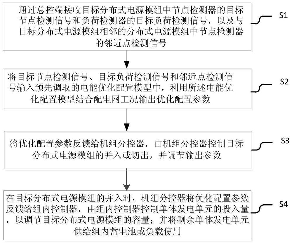
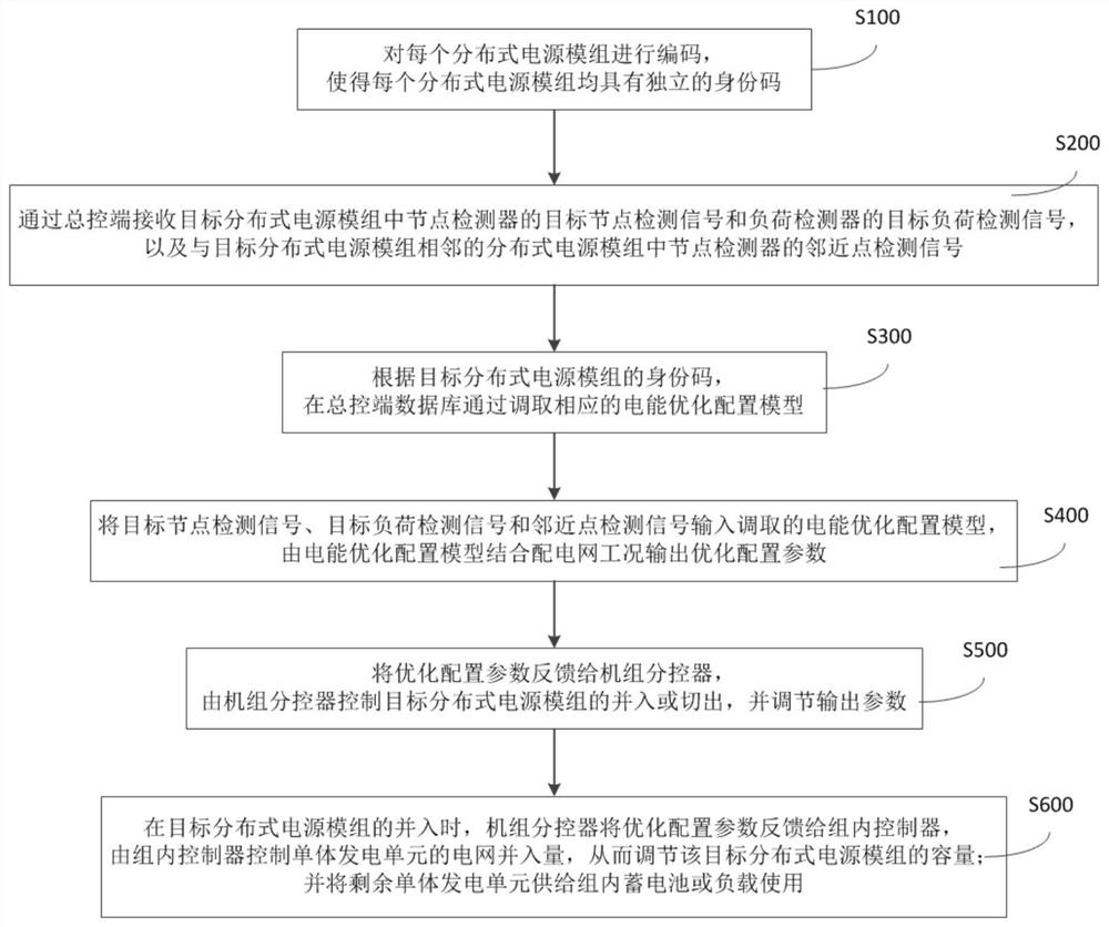
[0075] In this example, see figure 2 As shown, the present invention proposes a distributed power grid-connected power optimization distribution method, including steps:

[0076] S100, encoding each distributed power supply module so that each distributed power supply module has an independent identity code;

[0077] S200, receiving the target node detection signal of the node detector in the target distributed power supply module and the target load detection signal of the load detector through the master control terminal, and the nodes in the distributed power supply module adjacent to the target distributed power supply module The detector's proximity detection signal;

[0078] S300, according to the identity code of the target distributed power supply module, calls the corresponding power optimization configuration model in the master control terminal database;

[0079] S400, input the target node detection signal, the target load detection signal and the adjacent point...


PUM


Abstract

The invention discloses an electric energy optimal distribution method and system for grid connection of a distributed power supply. The method comprises the following steps: compiling an identity code for a distributed power supply module; obtaining a target node detection signal, a target load detection signal and an adjacent point detection signal; inputting the target node detection signal, the target load detection signal and the adjacent point detection signal into an electric energy optimal configuration model corresponding to the identity code, and outputting optimal configuration parameters by combining the electric energy optimal configuration model with the working condition of the power distribution network; and feeding back the optimal configuration parameters to a unit sub-controller, and controlling the target distributed power supply module for industrial control by the unit sub-controller. According to the invention, electric energy resource optimal configuration of the power distribution network with a plurality of distributed power supplies can be realized, and the states of the adjacent distributed power supplies are coordinated and adjusted, so that each distributed power supply provides the optimal electric energy ratio for the power grid, the supply states of the distributed power supplies are adjusted according to the actual operation state of the powergrid, and stable, safe and reliable operation of the power grid of the distributed power supplies can be ensured.

Description

technical field [0001] The invention belongs to the technical field of grid-connected distributed power sources, and in particular relates to a method system for optimal distribution of electric energy for grid-connected distributed power sources. Background technique [0002] At present, the global energy crisis is prominent, environmental pollution is serious, people are paying more and more attention to the natural environment, and clean distributed power generation technology is getting more and more attention. With the development of various new power generation technologies and the improvement of distributed power generation technology, its outstanding features such as high energy conversion efficiency, reduced investment cost, environmental friendliness, and good economic benefits have broad development space. [0003] The distributed generation (DG) using new energy to generate electricity can not only reduce the emission of pollutants, but also reduce the power loss...

Claims


Application Information

Patent Timeline
Patent Type & Authority Applications(China)
IPC IPC(8): H02J3/00H02J3/38H02J9/06
CPCH02J3/00H02J9/061
Inventor 孙艳霞何国庆刘纯孙文文张悦范瑞祥黎诗义
Owner CHINA ELECTRIC POWER RES INST
Why Eureka
Try Eureka