
Eureka
For R&D, Eureka makes reading and utilizing patents & technical documents easy.
Eureka AIR
Designed for self-driven R&D workflows. Generate viable solutions, solve complex R&D challenges, empower your innovation with AI.

Eureka Materials
Designed for material experts only. Revolutionize your material R&D, from search, analyze, to developing new materials.

TechResearch
Generate reliable direction feasibility study reports for your R&D in just a few steps.

TechSeek
Discover and master advanced knowledge NOW. Basics, ideas, possibilities, all at once.

TechMind
As an expert in R&D Theories, TechMind can generates customized viable solutions instantly.

TechRisk
Analyze your overall solution with one click, know your potential R&D risks in advance.

TechMonitor
Get weekly tech updates, stay abreast of the latest tech innovations and key insights.
Rotor and surface-magnet-type rotating electrical machine
A technology of rotor core and rotor is applied in the field of rotor and surface magnet type rotating electrical machine, which can solve the problems of reducing centrifugal force and reducing the holding strength of permanent magnet, and achieve the effect of suppressing falling off.
- Summary
- Abstract
- Description
- Claims
- Application Information
AI Technical Summary
Problems solved by technology
Method used
Image

Examples
Embodiment approach
[0042] (Surface magnet type rotating electrical machines)
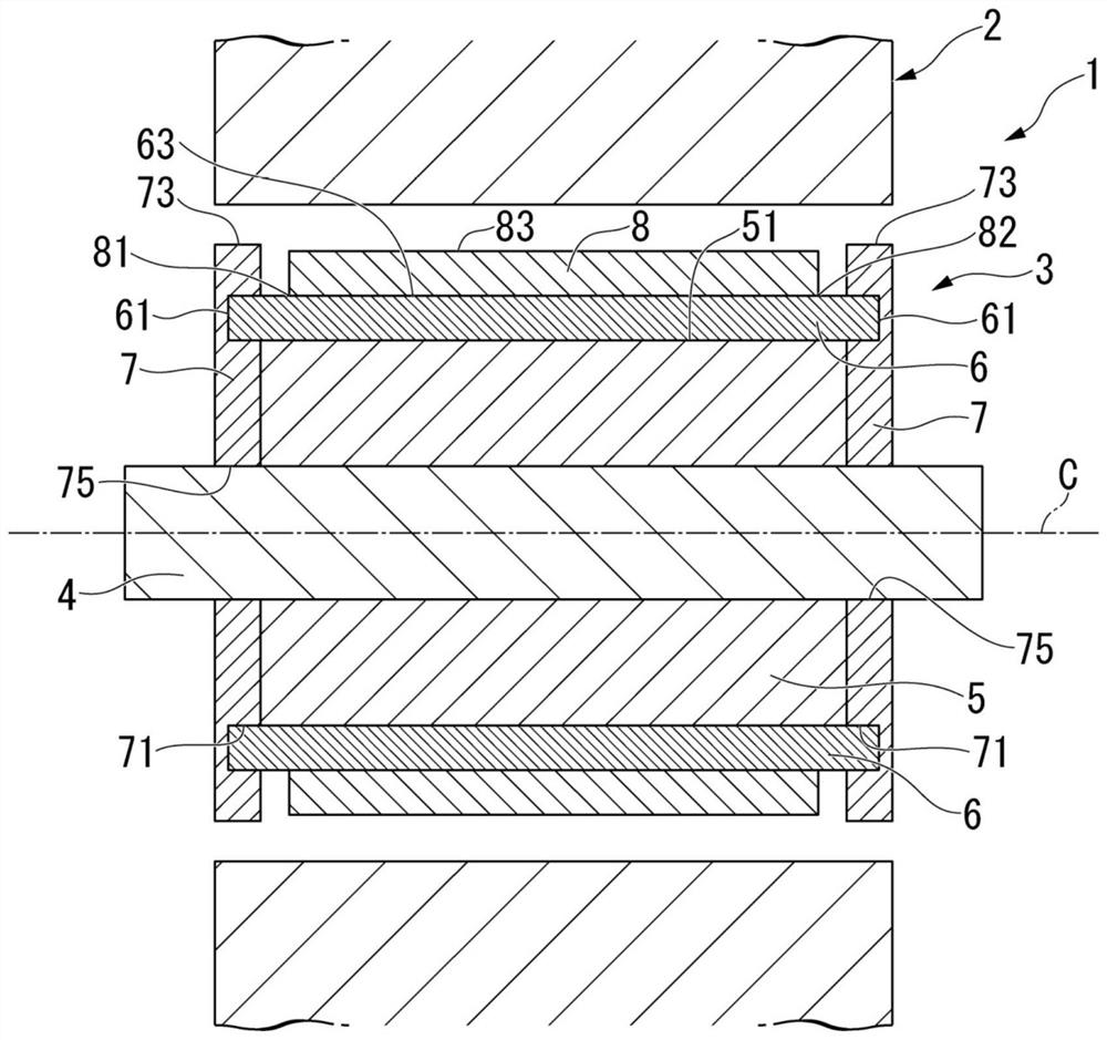
[0043] figure 1 It is a sectional view of the surface magnet type rotating electrical machine 1 of the embodiment.
[0044] The surface magnet type rotating electrical machine 1 is, for example, a running motor mounted in a vehicle such as a hybrid vehicle or an electric vehicle. However, the configuration of the present invention is not limited to a travel motor, and can be applied to a motor for power generation, a motor for other purposes, and a rotating electric machine (including a generator) other than for vehicles. The surface magnet type rotating electrical machine 1 is a so-called SPM (Surface Permanent Magnet) motor in which a permanent magnet 6 is arranged on an outer peripheral surface 51 of a rotor core 5 .
[0045] A surface magnet type rotating electrical machine 1 includes a stator 2 and a rotor 3 .
[0046] The stator 2 is formed in an annular shape with the axis C as the center. The stator 2 is ...
PUM
 Abstract
Description
Claims
Application Information
 - R&D Engineer
- R&D Manager
- IP Professional
- Industry Leading Data Capabilities
- Powerful AI technology
- Patent DNA Extraction
Browse by: Latest US Patents, China's latest patents, Technical Efficacy Thesaurus, Application Domain, Technology Topic, Popular Technical Reports.
© 2024 PatSnap. All rights reserved.Legal|Privacy policy|Modern Slavery Act Transparency Statement|Sitemap|About US| Contact US: help@patsnap.com