Fertilization equipment used for agricultural machinery and fertilization method used for agricultural machinery

A technology of agricultural machinery and equipment, which is applied in the field of fertilization equipment and fertilization for agricultural machinery, and can solve the problems of uncontrollable fertilization amount, large loss of fertilizer nutrients, and high utilization rate

Active Publication Date: 2020-10-30
湛江市恒发农业科技有限公司
View PDF8 Cites 4 Cited by
  • Summary
  • Abstract
  • Description
  • Claims
  • Application Information

AI Technical Summary

Problems solved by technology

[0004] The main basis for fertilization is soil fertility level, crop type, target yield, climate environment and fertilizer characteristics, so as to select the appropriate fertilizer, estimate the amount of fertilizer required, and determine the fertilization time and fertilization mode. According to the different fertilization time, it can be divided into Base fertilizer and top dressing can be divided into spreading, flushing, hole application, strip application, etc. according to different fertilization modes; spreading and flushing are conducive to the diffusion of nutrients and are convenient to apply, but the loss of nutrients is large and the utilization rate is low; Application and strip application have less nutrient loss and high utilization rate, but consume a certain amount of mechanical energy
[0005] With the development of modern precision agriculture, precision fertilization has also been developed rapidly and will become an important fertilization mode. When applying base fertilizer, the existing agricultural machinery fertilization equipment usually adopts the mode of spreading to improve soil fertility. However, when the existing device is fertilizing, the fertilizer is not evenly distributed, and the fertilizer is mostly applied on the surface of the soil, which has a small effect on the soil at the bottom, causing more nutrient loss of the fertilizer. The loose soil of the soil makes the effect of raising and absorbing waste materials poor, thus affecting the quality of fertilization. At the same time, some existing fertilization equipment is difficult to operate, and the manual operation is intensive, making it impossible to control the amount of fertilizer applied during fertilization. The improvement of the fertilizer has caused a great impact. Based on this, the present invention designs a fertilization equipment and fertilization method for agricultural machinery to solve the above problems

Method used


Image

  • Fertilization equipment used for agricultural machinery and fertilization method used for agricultural machinery
  • Fertilization equipment used for agricultural machinery and fertilization method used for agricultural machinery
  • Fertilization equipment used for agricultural machinery and fertilization method used for agricultural machinery

Examples


Embodiment 1

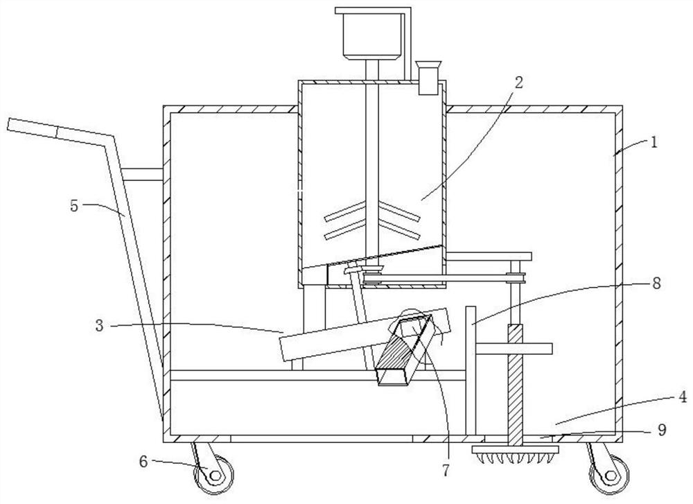
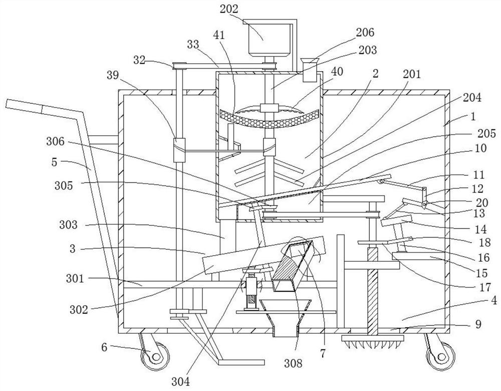
[0042] see Figure 1-9 , the present invention provides a technical solution: a fertilization equipment for agricultural machinery, comprising a device housing 1, a stirring mechanism 2, a uniform feeding mechanism 3 and a loosening mechanism 4, the left side of the device housing 1 is provided with a push rod 5, the device The bottom of shell 1 is equipped with moving wheel 6, and even feeding mechanism 3 is installed below stirring mechanism 2, and soil loosening mechanism 4 is installed in the right side of uniform feeding mechanism 3.

[0043] The stirring mechanism 2 comprises a stirring chamber 201, a servo motor 202, a stirring shaft 203, a stirring rod 204, a transmission chamber 205 and a feeding cylinder 206, the stirring chamber 201 is fixedly connected to the top of the device housing 1, and the transmission chamber 205 is arranged on the top of the stirring chamber 201. bottom, and the bottom of the mixing chamber 201 near the left end of the transmission chamber ...

Embodiment 2

[0048] On the basis of embodiment 1,

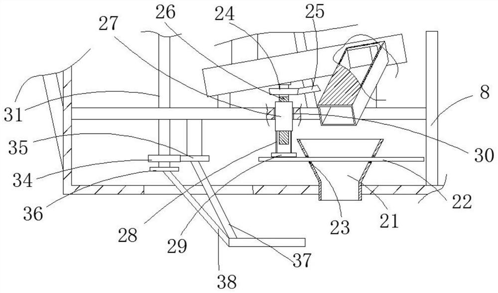
[0049] The bottom of the device shell 1 is also provided with a bulk material mechanism, which includes a discharge hopper 21, an arc-shaped sieve plate 22 and an elastic connecting ring 23. The discharge hopper 21 is inserted in the middle of the bottom of the device shell 1 and is located in the lower barrel. Below 308 , the arc-shaped sieve plate 22 is movably connected to the upper end of the discharge hopper 21 , and the elastic connecting ring 23 is installed on the outer wall of the discharge hopper 21 and located on the upper and lower sides of the arc-shaped sieve plate 22 .

[0050] Wherein, above the arc-shaped sieve plate 22, a vibrating mechanism is provided, and the vibrating mechanism includes a third main bevel gear 24, a third secondary bevel gear 25, a third rotating rod 26, a movable sleeve 27, a mounting rod 28 and an arc block. 29. The support plate 301 is provided with a square hole 30, and the third rotating rod 26 ...

Embodiment 3

[0053] On the basis of embodiment 2,

[0054] The left side of device housing 1 is also provided with earth-covering mechanism, and earth-covering mechanism comprises the second rotating rod 31, the second transmission wheel 32, the second conveyor belt 33, the gear plate 34, the first transmission disk 35, the second transmission disk 36, the first Soil-covering rod 37 and second soil-covering rod 38 (a section of the first soil-covering rod 37 and the second soil-covering rod 38 near the bottom surface is arc-shaped to improve the effect of gathering soil), the second rotating rod 31 is connected to the support plate 301 in rotation, And the top of the second rotating rod 31 extends to the top of the device housing 1, the second drive wheel 32 is provided with two groups, one group is installed on the top of the second rotating rod 31, and the other group is installed on the upper end of the stirring shaft 203, The second conveyor belt 33 is sleeved between two groups of sec...


PUM


Abstract

The invention provides fertilization equipment used for agricultural machinery and a fertilization method used for the agricultural machinery, and relates to the technical field of agricultural scarification and fertilization. The fertilization equipment used for the agricultural machinery comprises a device shell, a stirring mechanism, an even blanking mechanism and a scarification mechanism, wherein the even blanking mechanism is installed below the stirring mechanism, the scarification mechanism is installed on the right side of the even blanking mechanism, a stirring chamber is fixedly connected with the top of the device shell, a transmission chamber is arranged on the bottom of the stirring chamber, a discharging opening is formed in the position, close to the left end of the transmission chamber, on the bottom of the stirring chamber, a servo motor is installed on the top of the stirring chamber, one end of a stirring shaft is connected with an output end of the servo motor, theother end of the stirring shaft extends to an inner cavity of the transmission chamber, a stirring rod is welded to the stirring shaft, and a feeding cylinder communicates with the top of the stirring chamber. According to the fertilization equipment used for the agricultural machinery and the fertilization method used for the agricultural machinery, through various linkage parts, functions of stirring, blanking, scarification, earthing and the like are integrated into the whole device, operation is simple and convenient, the workload is small, fertilization is made to be easier, and the fertilization quality is guaranteed at the same time.

Description

technical field [0001] The invention relates to the technical field of agricultural soil loosening and fertilization, in particular to a fertilization equipment and a fertilization method for agricultural machinery. Background technique [0002] With the increase of the country's investment in the agricultural industry, agricultural mechanization has also ushered in a new opportunity for development. Based on the understanding of agricultural machinery and the application status of agricultural machinery, the application range of agricultural machinery is gradually expanding. Both the quantity and the types of applications are increasing year by year. The overall industry status of agricultural machinery is relatively optimistic. Based on the promotion effect of agricultural machinery on agricultural production, agricultural machinery has become an inseparable and important part of agricultural production and has an irreplaceable role in agricultural production. It not only ...

Claims


Application Information

Patent Timeline
Patent Type & Authority Applications(China)
IPC IPC(8): A01B49/06A01C15/12A01C15/00B02C18/10B02C18/18B02C23/16
CPCA01B49/06A01C15/12A01C15/005A01C15/00B02C18/10B02C18/18B02C23/16B02C2023/165
Inventor 梁伟
Owner 湛江市恒发农业科技有限公司
Why Eureka
Try Eureka