Pipeline butt joint system, cleaning robot and workstation
A technology of pipelines and joints, which is applied in the field of pipeline connection auxiliary equipment, to achieve the effect of good sealing and not easy to leak
- Summary
- Abstract
- Description
- Claims
- Application Information
AI Technical Summary
Problems solved by technology
Method used
Image

Examples
Embodiment approach 1
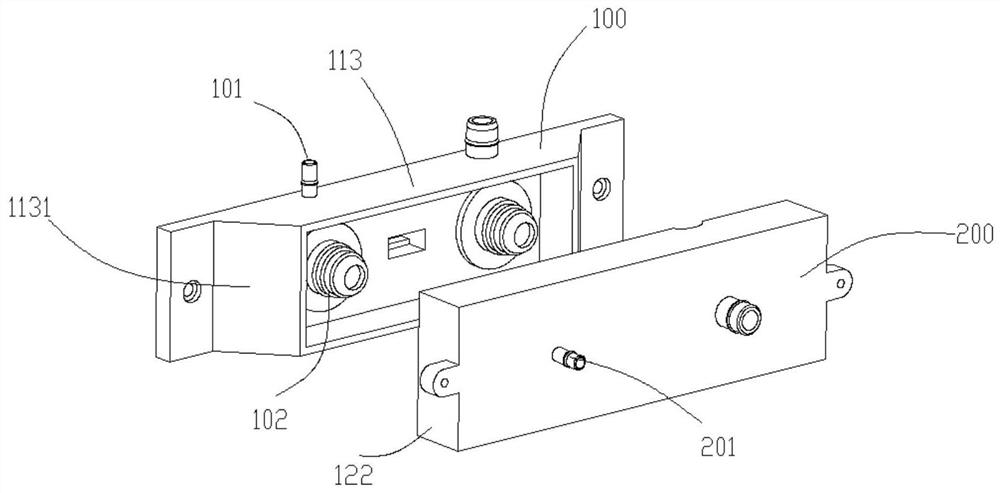
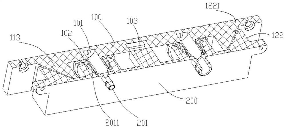
[0066] Such as Figure 1A and Figure 1B As shown, in one embodiment, the first limit seal assembly includes at least one conical sealing ring 102, and the conical sealing ring 102 is sleeved on the docking port of the first joint 101; the docking port of the second joint 201 is Trumpet-shaped interface 2011 ; wherein, the horn-shaped interface 2011 is compatible with the tapered sealing ring 102 .
[0067] In this embodiment, the trumpet-shaped interface 2011 has a large front opening and a small rear opening; the conical sealing ring has a large front opening and a small rear opening. When the second joint seat 200 is close to the first joint seat 100, the smaller rear opening of the tapered sealing ring can easily fall into the larger horn-shaped interface 2011 at the front mouth, and then pass through the horn-shaped interface 2011 and The cooperation of the conical sealing ring 102 enables the first joint 101 and the second joint 201 to be butted and communicated quickly...
Embodiment approach 2
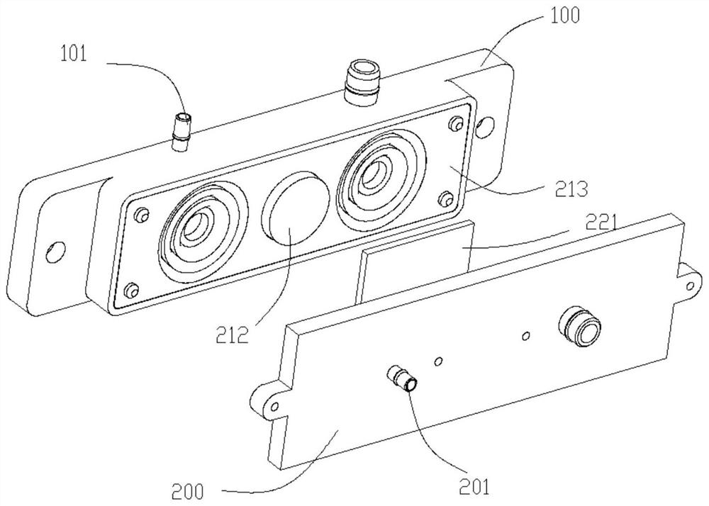
[0077] Such as Figure 2A and Figure 2B As shown, the first position-limiting sealing assembly includes a gasket 213 and a first magnetic member 212. The gasket 213 is fixed on the outside of the first joint seat 100 and sleeved outside the first joint 101. The docking port of the first joint 101 flush with the gasket 213.
[0078] The second limiting seal assembly includes a second magnetic component 221 , and the position of the second magnetic component 221 is adapted to the position of the first magnetic component 212 .
[0079] In this embodiment, the gasket 213 is sheathed outside the first joint 101 , and when the second joint 201 is docked with the first joint 101 , the second joint seat 200 or the second joint 201 is close to the gasket 213 . Then, through the mutual attraction of the first magnetic component 212 and the second magnetic component 221 , the second joint seat 200 or the second joint 201 is pressed against the gasket 213 , and the sealing is realized ...
Embodiment approach 3
[0083] Such as Figure 3A and Figure 3B As shown, the first limit sealing assembly includes a first sealing ring 313 , a one-way valve 314 , a second sealing ring 315 and a one-way valve pressure block 316 ; the first sealing ring 313 is sleeved in the docking port of the first joint 101 One end of the one-way valve 314 is socketed in the first sealing ring 313 , the other end of the one-way valve 314 is socketed in the second sealing ring 315 , and the one-way valve pressing block 316 is socketed outside the first sealing ring 313 .
[0084] When the second joint seat 200 is close to the first joint seat 100, the docking port of the second joint 201 passes through the one-way valve pressure block 316 and the second sealing ring 315, and pushes the switch of the one-way valve 314, so that the first A joint 101 communicates with a second joint 201 .
[0085] In this embodiment, a stepped seat against the first sealing ring 313 is provided in the docking port of the first joi...
PUM
 Abstract
Description
Claims
Application Information
 - R&D
- Intellectual Property
- Life Sciences
- Materials
- Tech Scout
- Unparalleled Data Quality
- Higher Quality Content
- 60% Fewer Hallucinations
Browse by: Latest US Patents, China's latest patents, Technical Efficacy Thesaurus, Application Domain, Technology Topic, Popular Technical Reports.
© 2025 PatSnap. All rights reserved.Legal|Privacy policy|Modern Slavery Act Transparency Statement|Sitemap|About US| Contact US: help@patsnap.com