Mud removal equipment for industrial wastewater treatment

A technology for industrial waste water and equipment, applied in filtration and separation, fixed filter element filters, chemical instruments and methods, etc., can solve the problems of sludge pollution, corrosion, incomplete sludge removal, equipment damage, etc., and improve the sludge removal effect. , Avoid corrosive damage, reduce the effect of pressure

Inactive Publication Date: 2020-10-30
广州德程智能科技股份有限公司
View PDF8 Cites 0 Cited by
  • Summary
  • Abstract
  • Description
  • Claims
  • Application Information

AI Technical Summary

Problems solved by technology

[0003] In view of the above, it is difficult for some wastewater desilting equipment on the market to effectively purify wastewater. Among them, some sludge inside the industrial wastewater has strong adhesion and will be adsorbed on the inner wall of the equipment, so that the wastewater cannot periodically enter the For desilting equipment, it is difficult to perform pressure filtration treatment on wastewater, resulting in incomplete desilting, and most of the sludge is polluting and corrosive, and long-term adsorption on the inner wall of the equipment will cause equipment damage. The invention provides an industrial wastewater treatment desilter equipment

Method used


Image

  • Mud removal equipment for industrial wastewater treatment
  • Mud removal equipment for industrial wastewater treatment
  • Mud removal equipment for industrial wastewater treatment

Examples


Embodiment 1

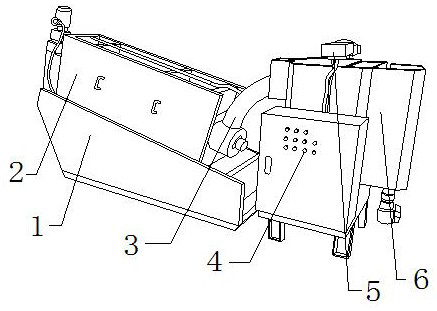
[0024] Such as Figure 1-Figure 4 Shown:

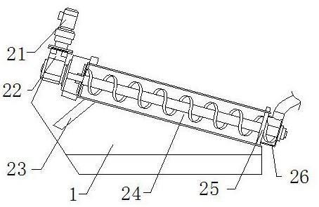
[0025] The present invention provides a desilting equipment for industrial wastewater treatment, the structure of which includes a fixed seat 1, a desilter 2, a mud inlet pipe 3, a control electric box 4, an extractor 5, and a storage box 6. The extractor 5 and the control The electrical box 4 is electrically connected, the storage box 6 is connected to the desilter 2 through the mud inlet pipe 3, the extractor 5 is bolted to the top of the storage box 6, and the mud inlet pipe 3 is nested and connected to the desilter The side of the machine 2, the desilter 2 is embedded and connected to the top of the fixed seat 1, and the desilter 2 mainly includes a motor 21, a rotator 22, a dumping plate 23, a desilter device 24, an isolation plate 25, a temporary Storage box 26, the motor 21 is mechanically connected to the top of the rotor 22, the desilter device 24 is nested and connected to the side of the rotor 22, and the temporary storage...

Embodiment 2

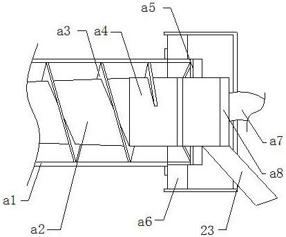
[0031] Such as Figure 5-Figure 7 Shown:

[0032] The present invention provides a desilting equipment for industrial wastewater treatment, the structure of which includes a fixed seat 1, a desilter 2, a mud inlet pipe 3, a control electric box 4, an extractor 5, and a storage box 6. The extractor 5 and the control The electrical box 4 is electrically connected, the storage box 6 is connected to the desilter 2 through the mud inlet pipe 3, the extractor 5 is bolted to the top of the storage box 6, and the mud inlet pipe 3 is nested and connected to the desilter The side of the machine 2, the desilter 2 is embedded and connected to the top of the fixed seat 1, and the desilter 2 mainly includes a motor 21, a rotator 22, a dumping plate 23, a desilter device 24, an isolation plate 25, a temporary Storage box 26, the motor 21 is mechanically connected to the top of the rotor 22, the desilter device 24 is nested and connected to the side of the rotor 22, and the temporary storage...


PUM


Abstract

The invention discloses mud removal equipment for industrial wastewater treatment. The mud removal equipment structurally comprises a fixed seat stand, a mud remover, a mud inlet pipe, a control electric box, an extractor and a storage box, wherein the mud remover is embedded in and fixedly connected with the top end of the fixed seat stand; the mud remover comprises a motor, a rotator, a dumpingplate, a mud removal device, an isolation plate and a temporary storage box; and the mud removal device is connected to the side of the rotator in a nesting manner. According to the invention, a rotating rod rotates and operates, and a spiral push plate pushes the wastewater forwards to allow the wastewater to reach the area of the mud removal device; the extrusion work of the spiral push plate isperformed, so sludge can be quantitatively removed; angle blocks can be used for removing sludge adsorbed on the spiral push plate; due to the fact that the sludge is carried in the wastewater and filtered by a barrier plate, the sludge is adsorbed at the tail end of a pipe body; and an extension rod drives a lantern ring to move, and an inclined knife is arranged at the top end of the lantern ring and attached to the barrier plate, so the sludge adsorbed on the barrier plate can be effectively scraped, and corrosive damage of the sludge to the equipment is avoided.

Description

technical field [0001] The invention relates to the field of industrial wastewater treatment, and more specifically relates to an industrial wastewater treatment desilting equipment. Background technique [0002] Wastewater, usually refers to polluted discharge water. Wastewater mainly includes domestic wastewater and industrial wastewater. In industrial wastewater treatment, it is necessary to treat the sludge inside the wastewater in order to purify the wastewater in the next step. Due to the fact that some wastewater on the market It is difficult for desilter equipment to effectively purify wastewater. Part of the sludge inside industrial wastewater has strong adhesion, and it will be adsorbed on the inner wall of the equipment, so that the wastewater cannot periodically enter the desilter equipment and pressurize the wastewater. Filtration treatment is difficult, resulting in incomplete desilting, and most of the sludge is polluting and corrosive, and long-term adsorptio...

Claims


Application Information

Patent Timeline
Patent Type & Authority Applications(China)
IPC IPC(8): B01D29/01B01D29/64B01D29/82B01D29/94
CPCB01D29/01B01D29/6469B01D29/828B01D29/94
Inventor 王云力
Owner 广州德程智能科技股份有限公司
Why Eureka
Try Eureka