
Double-servo plunger type quantifying machine

A plunger-type, double-servo technology, applied in the field of double-servo plunger-type dosing machines, can solve the problems of low production efficiency, lower product yield, unstable mixing ratio and adequacy, etc.

Active Publication Date: 2020-10-30
存融流体设备(无锡)有限公司
View PDF8 Cites 6 Cited by
  • Summary
  • Abstract
  • Description
  • Claims
  • Application Information

AI Technical Summary

Problems solved by technology

[0003] Aiming at the above-mentioned technical problems, the present invention provides a dual-servo plunger-type dosing machine to solve the problem in the prior art that the labor intensity of the operator is high due to the manual mixing of glue, and it is easy to cause the proportion and adequacy of the glue mixing to be high. The problem of instability avoids the occurrence of poor bonding of product parts, low production efficiency, and reduced product yield

Method used


Image

  • Double-servo plunger type quantifying machine
  • Double-servo plunger type quantifying machine
  • Double-servo plunger type quantifying machine

Examples


Embodiment 1

[0041] In the traditional production process, manual glue mixing is mainly used. The operator needs to pour the filling glue A and B glue into the glue mixing cup in the specified ratio, and then mix the glue fully by the continuous stirring of the glue stick, and then use the glue stick to mix The mixed AB glue is applied to the parts. However, because the setting time of AB glue is usually short after mixing, in order to avoid waste of glue, the operator can only mix the amount of glue that can be used within a certain period of time, resulting in greater labor intensity for the operator and easy mixing. The glue ratio and sufficiency are not stable (especially when the amount of glue is relatively large), which will eventually lead to poor bonding of product parts, low production efficiency, and reduced product yield.

[0042] In order to solve the problem that the manual mixing of glue in the prior art leads to greater labor intensity of the operator, and it is easy to cause ...

Embodiment 2

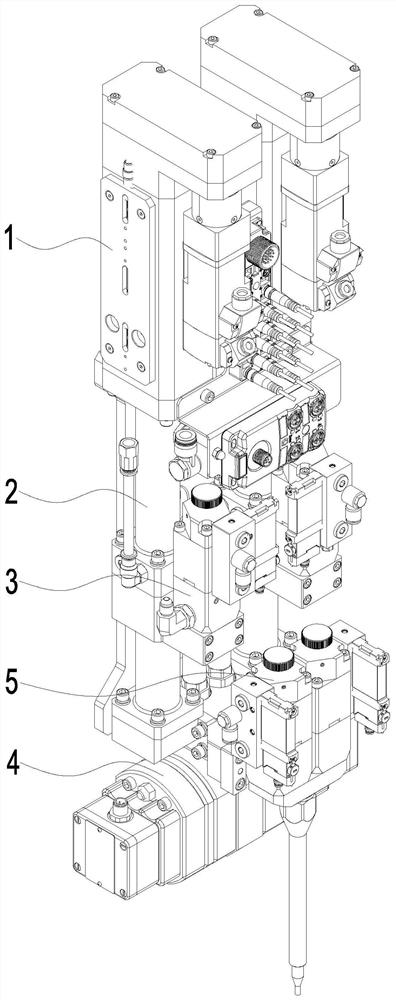
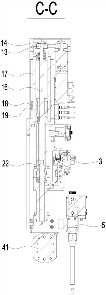
[0055] In order to facilitate the precise control of the amount of glue, the proportion of glue and the speed of glue from the feed valve 3, further, such as Figure 8-12 As shown, the feed valve 3 includes a cylinder body 31 and a solenoid valve 32; the cylinder body 31 and the solenoid valve 32 are of an integrated structure; the cylinder body 31 and the metering mechanism 2 are provided in a communicable manner. Through the design of the integrated solenoid valve 32, the solenoid valve 32 and the cylinder body 31 have an integrated structure, that is, there is no communicating air pipe between the two, thereby avoiding the delay problem when the cylinder is opened and closed. 3Accurate control of the amount of glue, the proportion of glue and the speed of glue provide the basis.

[0056] At present, the valve needles 33 used for the feed valve 3 on the market are all tie rod type or V-shaped ends, and these types of valve needles 33 will discharge more fluid during the process ...

Embodiment 3

[0060] On the basis of Example 2, such as Figure 13-16 As shown, the mixing valve 5 is an integrated design of multiple feed valves 3. The mixing valve 5 in this embodiment is specifically designed by integrating two feed valves 3, and the mixing valve 5 obtained by integrating two feed valves 3 can be used independently or in combination with any two-component static mixing system. It can be used in combination according to actual usage scenarios and conditions.


PUM


Abstract

The invention relates to the field of quantifying equipment, in particular to a double-servo plunger type quantifying machine. The quantifying machine comprises a power mechanism, a metering mechanism, a feeding valve, a flow monitoring system used for monitoring various parameters of fluid and a mixing valve; the metering mechanism is movably arranged on the power mechanism; the feeding valve communicates with the metering mechanism; the flow monitoring system communicates with the metering mechanism; the mixing valve is communicably disposed with the flow monitoring system. According to thequantifying machine, on one hand, the flow monitoring system and the quantifying machine are integrally designed, so that no pipeline needs to be arranged between the whole quantifying machine and theflow monitoring system, namely, no pressure loss is generated when fluid flows, and the flow monitoring system can monitor technological parameters such as the glue outlet proportion, the glue outletamount and the glue outlet speed in real time, and therefore the accuracy and sufficiency of glue mixing can be improved; and on the other hand, the automatic operation level of glue injection and glue mixing is improved, and the problems that the labor intensity of manual glue mixing is high, and the production efficiency is low are solved.

Description

Technical field [0001] The invention relates to the technical field of quantitative equipment, in particular to a double-servo plunger type quantitative machine. Background technique [0002] With the advancement of science and technology, the requirements of manufactured products are becoming more and more sophisticated, and the requirements of manufacturers for the dispensing process of mixed glue are getting higher and higher. In the traditional production process, manual glue mixing is mainly used. The operator needs to pour the filling glue A and B glue into the glue mixing cup in the specified ratio, and then mix the glue fully by the continuous stirring of the glue stick, and then use the glue stick to mix The mixed AB glue is applied to the parts. However, because the setting time of AB glue is usually short after mixing, in order to avoid waste of glue, the operator can only mix the amount of glue that can be used within a certain period of time, resulting in greater la...

Claims


Application Information

Patent Timeline
IPC IPC(8): B05C5/02B05C11/10
CPCB05C5/02B05C5/0225B05C11/1036B05C11/1026
Inventor 欧阳素
Owner 存融流体设备(无锡)有限公司
Learn More