Method for improving physical dimension precision of pipe body and pipe ends of longitudinally welded pipe

A technology of geometric size, straight seam welded pipe, applied in the field of pipeline steel pipe manufacturing, can solve problems such as difficulty in adapting to the rapid development of pipeline construction, high geometrical accuracy requirements of welded pipes, and large resilience of thick-walled straight seam welded pipes, etc. Error avoidance and excellent precision

Inactive Publication Date: 2020-10-30
BC P INC CHINA NAT PETROLEUM CORP +1
View PDF5 Cites 0 Cited by
  • Summary
  • Abstract
  • Description
  • Claims
  • Application Information

AI Technical Summary

Problems solved by technology

For the welding method of pipeline girth weld on site, traditional manual welding has been difficult to adapt to the rapid development of pipeline construction, and it is imperative to promote the use of fully automatic girth weld welding
However, the automatic welding of girth welds requires high geometrical precision of welded pipes, which poses a higher challenge for the manufacture of high-grade, large-diameter, and thick-walled welded pipes.
[0003] For the manufacture of high-grade, large-diameter, thick-walled longitudinally welded pipes, due to the continuous optimization of pipeline steel plate composition and rolling process, as well as the continuous improvement of welding materials, there are fewer problems in welding, but in terms of geometric dimension control of welded pipes There is room for further improvement
High-grade thick-walled pipeline steel is a multi-component alloy, which is prone to defects such as pouting and misalignment during the forming process; thick-walled longitudinal seam welded pipes have a large resilience during JCO forming, and the pipe shape is difficult to control. This is especially true for thick thick-walled pipeline steel

Method used


Image

  • Method for improving physical dimension precision of pipe body and pipe ends of longitudinally welded pipe
  • Method for improving physical dimension precision of pipe body and pipe ends of longitudinally welded pipe
  • Method for improving physical dimension precision of pipe body and pipe ends of longitudinally welded pipe

Examples


Embodiment 1

[0018] Example 1: Control of geometric dimension accuracy of X80 OD1422×25.7mm longitudinal welded pipe.

[0019] (1) Select the X80 thick-walled pipeline steel plate with a wall thickness of 25.7mm. The unevenness of the steel plate is required to be less than 10mm / 2000mm.

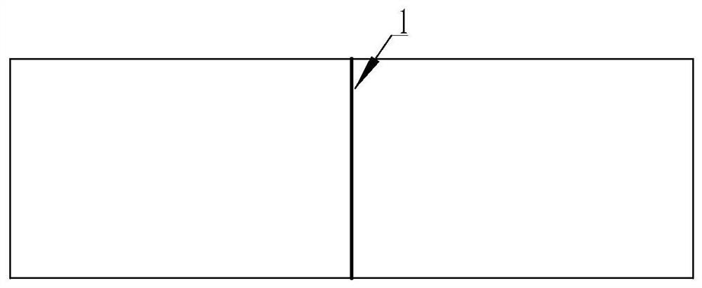
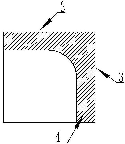
[0020] (2) When JCO is formed, use such as figure 1 and figure 2 The molded centering block shown is a hollow structure with a figure 2 Medium polyurethane material 4, placed in figure 1 At position 1 of the center line, during the process of pressing the steel plate from the J type to the C type and O type, after each pressing, the centering block is used to push the welded pipe to the center of the forming machine, and the centering block is used to push the welded pipe to the center of the forming machine. figure 2 Multi-angle centering is carried out on the center line 2 and the front centering position 3 on the middle and upper surface to ensure that the welded pipe is always in the center of t...

Embodiment 2

[0029] Example 2: Control of geometric dimension accuracy of X80 OD1422×30.8mm longitudinal welded pipe.

[0030] (1) Select the X80 thick-walled pipeline steel plate with a wall thickness of 30.8mm. The unevenness of the steel plate is required to be less than 10mm / 2000mm.

[0031] (2) When JCO is formed, it is used as shown in the attached drawing of the specification figure 1 and figure 2 The molded centering block shown is a hollow structure with a figure 2 Medium polyurethane material 4, placed in figure 1 At position 1 of the center line, during the process of pressing the steel plate from the J type to the C type and O type, after each pressing, the centering block is used to push the welded pipe to the center of the forming machine, and the centering block is used to push the welded pipe to the center of the forming machine. figure 2 Multi-angle centering is carried out on the center line 2 and the front centering position 3 on the middle and upper surface to ens...

Embodiment 3

[0040] Example 3: Control of geometric dimension accuracy of X80 OD1422×32.1mm longitudinal welded pipe.

[0041] (1) Select the X80 thick-walled pipeline steel plate with a wall thickness of 32.1mm. The unevenness of the steel plate is required to be less than 10mm / 2000mm.

[0042] (2) When JCO is formed, it is used as shown in the attached drawing of the specification figure 1 and figure 2 The molded centering block shown is a hollow structure with a figure 2 Medium polyurethane material 4, placed in figure 1 At position 1 of the center line, during the process of pressing the steel plate from the J type to the C type and O type, after each pressing, the centering block is used to push the welded pipe to the center of the forming machine, and the centering block is used to push the welded pipe to the center of the forming machine. figure 2 Multi-angle centering is carried out on the center line 2 and the front centering position 3 on the middle and upper surface to ens...


PUM

PropertyMeasurementUnit
thicknessaaaaaaaaaa
Eccentricityaaaaaaaaaa
thicknessaaaaaaaaaa

Abstract

The invention discloses a method for improving the physical dimension precision of the pipe body and pipe ends of a longitudinally welded pipe. The method comprises the steps that modular subdivisioncontrol is adopted during mechanical diameter expanding, different diameter expanding rates are adopted for the pipe ends and the pipe body, the diameter expanding length of each subsection is about 2.5-3.0 m during pipe body diameter expanding, it is guaranteed that the overlapping amount of last and next subsection diameter expanding is larger than 0.5 m, and the straightness deviation of the steel pipe within the overall length range is optimally controlled to be smaller than or equal to 0.15% of the pipe length. According to the method, different diameter expanding rates are adopted according to the diameter expanding requirements of different positions, difference control over the physical dimension of the pipe ends and the pipe body can be achieved, and the diameter expanding effectand quality of the whole pipe are guaranteed.

Description

Technical field: [0001] The invention belongs to the field of pipeline steel pipe manufacturing, and in particular relates to a method for improving the geometric dimension accuracy of a pipe body and a pipe end of a straight seam welded pipe. Background technique: [0002] Due to the constraints of environmental protection, land and other factors and the continuous pursuit of long-distance transmission efficiency and economy, the pipeline industry is increasingly developing in the direction of high steel grade, large diameter, and thick wall. For the welding method of the pipeline's on-site girth weld, traditional manual welding has been difficult to adapt to the rapid development of pipeline construction, and it is imperative to promote the use of fully automatic girth weld welding. However, the automatic welding of girth welds requires high geometrical precision of welded pipes, which poses a higher challenge for the manufacture of high-grade, large-diameter, thick-walled...

Claims


Application Information

Patent Timeline
Patent Type & Authority Applications(China)
IPC IPC(8): B21D39/08B21C37/08B21C51/00
CPCB21C37/08B21C51/00B21D39/08
Inventor 刘斌毕宗岳韦奉赵红波刘云张峰田磊席敏敏张超赵勇牛爱军黄晓辉袁兴龙
Owner BC P INC CHINA NAT PETROLEUM CORP
Why Eureka
Try Eureka