
Annular diamond wire saw cutting machine

A diamond wire, saw cutting machine technology, applied in metal sawing equipment, sawing machine equipment, stone processing equipment and other directions, can solve the problems of broken wire, discontinuous cutting process, cutting line impact and so on

Pending Publication Date: 2020-10-30
壶关高测新材料科技有限公司
View PDF0 Cites 3 Cited by
  • Summary
  • Abstract
  • Description
  • Claims
  • Application Information

AI Technical Summary

Problems solved by technology

[0003] One of the cutting methods is to drive the diamond wire to move at high speed, and at the same time, there is a relative linear motion between the workpiece and the diamond wire to realize the feed motion to realize cutting. The length of the diamond cutting wire participating in the cutting is the width of the workpiece in the cutting area. When the workpiece When the width is too large, the diamond cutting wire involved in cutting is too long, resulting in excessive cutting force and breaking of the cutting wire. Therefore, in order to reduce the cutting force, a lower feed speed is usually used, which affects the cutting efficiency.
[0004] There is also a cutting method is rotary cutting, through the slow rotation of the workpiece to make the cutting line and the workpiece form a circular tangent, reducing the length of the cutting line involved in cutting, but because the cutting line involved in the cutting is located in the middle of the guide wheel, the distance from the guide wheel It is far away and the wire bow is large, which affects the cutting efficiency. At the same time, when the irregularly shaped cutting piece is rotated and cut, the whole cutting process is discontinuous due to the shape of the cutting piece. Sometimes the cutting line is in contact with the cutting piece, and sometimes the cutting line and the cutting piece The parts are not in contact, so the cutting wire will be impacted, causing the wire to break

Method used


Image

  • Annular diamond wire saw cutting machine
  • Annular diamond wire saw cutting machine
  • Annular diamond wire saw cutting machine

Examples


Embodiment Construction

[0025] In order to make those skilled in the art better understand the technical solution of the present invention, the technical solution of the present invention is clearly and completely described below in conjunction with the accompanying drawings of the present invention. Based on the embodiments in this application, those of ordinary skill in the art will Other similar embodiments obtained without creative work shall all fall within the scope of protection of this application. In addition, the directional words mentioned in the following embodiments, such as "upper", "lower", "left", "right", etc., are only referring to the directions of the drawings, therefore, the directional words used are for illustration rather than limitation invent.

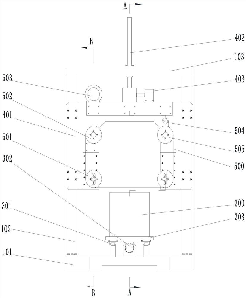
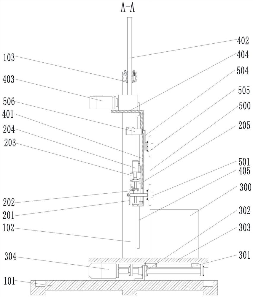
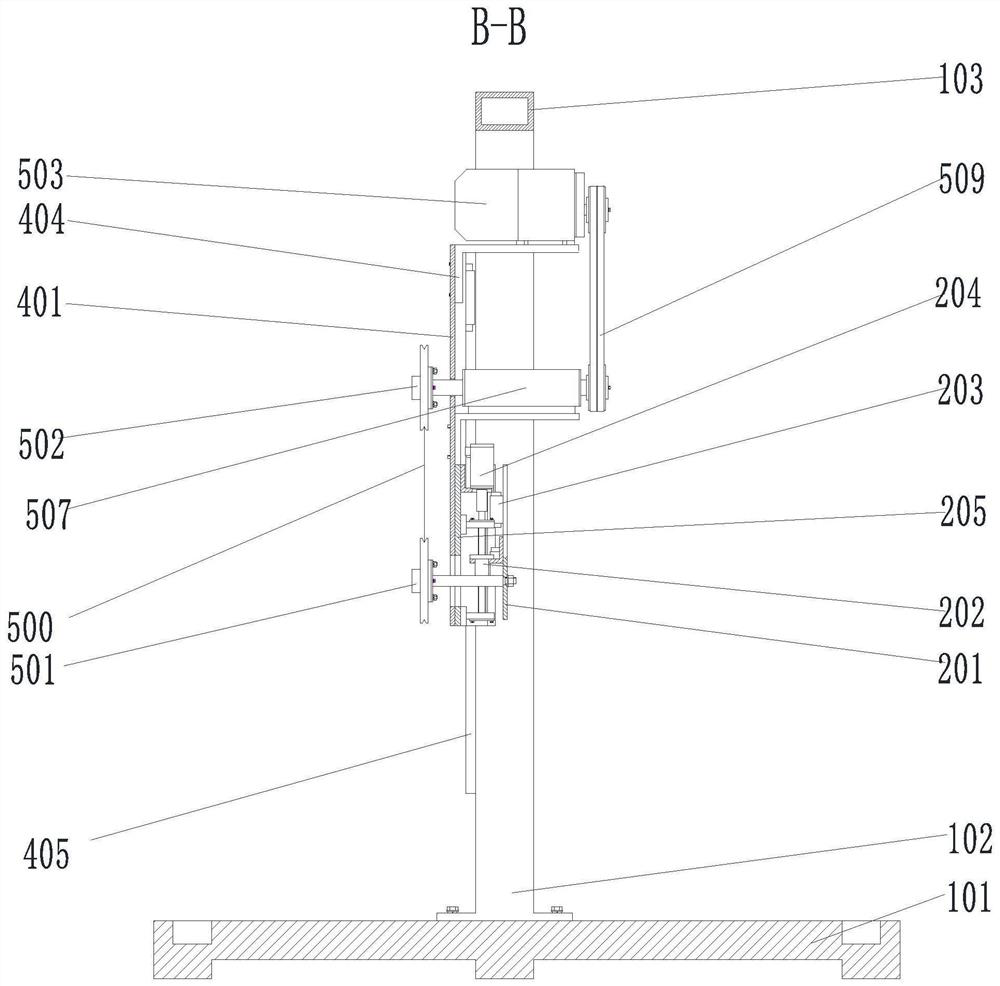
[0026] Such as Figure 1-Figure 4 Shown is that the present invention provides a circular diamond wire saw cutting machine, which includes a cutting machine frame, a workbench system arranged on the cutter frame for placing a workpi...


PUM


Abstract

The invention discloses an annular diamond wire saw cutting machine. The annular diamond wire saw cutting machine comprises a cutting machine frame, a worktable system arranged on the cutting machineframe and used for placing a to-be-cut workpiece, and a cutting system arranged above the worktable system and used for cutting the workpiece. The cutting machine moves up and down alternately throughtwo guiding wheels, the swinging of the part, participating in cutting, of a diamond wire between the two guiding wheels is achieved, the cutting force of the diamond wire is reduced, the diamond wire is prevented from breaking, meanwhile the contact area between a cutting line and the workpiece is constantly changed due to the alternating movement of the guiding wheels, the fatigue fracture of the diamond wire can be prevented, meanwhile the continuous contact with the workpiece can also be ensured, the situation that due to the irregular workpiece, the diamond wire and the workpiece sometimes are in contact and sometimes are separated, resulting in the impact of each contact, and leading to the fracture of the diamond wire is avoided, and thus the cutting machine is suitable for regularworkpiece cutting, also suitable for irregular workpiece cutting, and suitable for promotion.

Description

technical field [0001] The invention belongs to the technical field of wire saw cutting, and in particular relates to an annular diamond wire saw cutting machine. Background technique [0002] Ring diamond wire saw cutting machine is a cutting device that uses ring diamond wire as a cutting tool. [0003] One of the cutting methods is to drive the diamond wire to move at high speed, and at the same time, there is a relative linear motion between the workpiece and the diamond wire to realize the feed motion to realize cutting. The length of the diamond cutting wire participating in the cutting is the width of the workpiece in the cutting area. When the workpiece When the width is too large, the diamond cutting wire involved in cutting is too long, resulting in excessive cutting force and breaking of the cutting wire. Therefore, in order to reduce the cutting force, a lower feed speed is usually used, which affects the cutting efficiency. [0004] There is also a cutting meth...

Claims


Application Information

Patent Timeline
IPC IPC(8): B23D57/00B28D1/08B28D7/00B28D5/04
CPCB23D57/00B23D57/0061B23D57/0069B28D1/08B28D5/0058B28D5/042B28D7/00
Inventor 高伟王东雪张秋明
Owner 壶关高测新材料科技有限公司
Learn More