
Laser welding feeding and positioning device

A technology of laser welding and positioning device, used in laser welding equipment, auxiliary devices, welding equipment, etc., can solve the problems of work injury, lack of positioning device, incomplete workpiece welding, etc.

Inactive Publication Date: 2020-10-30
DONGGUAN UNIV OF TECH
View PDF7 Cites 1 Cited by
  • Summary
  • Abstract
  • Description
  • Claims
  • Application Information

AI Technical Summary

Problems solved by technology

[0004] The purpose of the present invention is to provide a laser welding feeding positioning device to solve the traditional laser welding equipment proposed in the background art. During the welding process, the adjustment of the position of the laser welding nozzle is too complicated, resulting in inaccurate welding positions. The raw materials will be placed in the laser operation position manually, which is easy to cause damage to the work. At the same time, the lack of positioning devices on the laser operation table will easily lead to accuracy problems during laser welding, resulting in incomplete welding of the workpiece, thus affecting the entire device. work efficiency problem

Method used


Image

  • Laser welding feeding and positioning device
  • Laser welding feeding and positioning device
  • Laser welding feeding and positioning device

Examples


Embodiment Construction

[0027] The technical solutions in the embodiments of the present invention will be clearly and completely described below in conjunction with the accompanying drawings in the embodiments of the present invention. Obviously, the described embodiments are only some of the embodiments of the present invention, not all of them. Based on The embodiments of the present invention and all other embodiments obtained by persons of ordinary skill in the art without making creative efforts belong to the protection scope of the present invention.

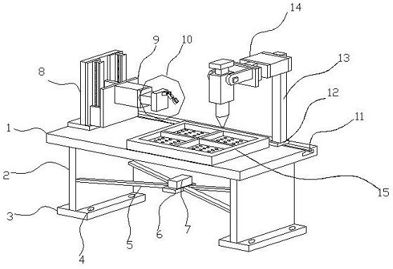
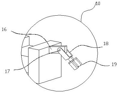
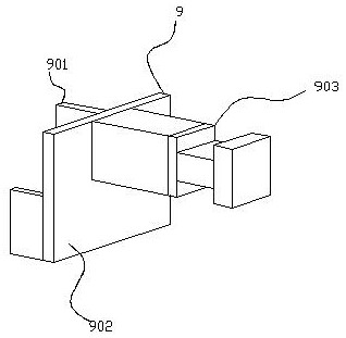
[0028] see Figure 1-6, the present invention provides a technical solution: a laser welding feeding positioning device, including a device main body 1 and a clamping mechanism 19, a bottom bracket 2 is connected to the bottom of the device main body 1, and a tripod is arranged on the right side of the bottom bracket 2 5. There are two sets of tripods 5, and the two sets of tripods 5 have a centrally symmetrical structure. Its triangular stable...


PUM

PropertyMeasurementUnit
Rotation angleaaaaaaaaaa

Abstract

The invention discloses a laser welding feeding and positioning device. The device comprises a device body and a clamping mechanism; bottom brackets are connected with the bottom of the device body; atripod is arranged on the right side of the bottom brackets and a motor platform is arranged on the right side of the tripod; a motor is arranged at the top of the motor platform; bases are connectedwith the bottoms of the bottom brackets; fixed screws are arranged at the tops of the bases; a slide rail is arranged on the left side of the top of the device body; and a sliding extensible mechanism is arranged on the right side of the slide rail. Through the arrangement of the slide rail and the sliding extensible mechanism, the device body constitutes a movably upward adjustment function; inoperation of the device, vertical sliding can be realized by collaborative operation of the slide rail and a sliding plate; and with the addition of an extensible structure of an extensible pillar, aclamped workpiece can be move from left to right to a processing position, so manual operation of a worker is not required, the operation efficiency of the device is improved, and safety of the workeris guaranteed.

Description

technical field [0001] The invention relates to the technical field of laser welding, in particular to a laser welding feeding and positioning device. Background technique [0002] Laser equipment mainly involves laser cutting and laser welding. Laser welding is an efficient and precise welding method that uses a high-energy-density laser beam as a heat source. Laser welding is one of the important aspects of the application of laser material processing technology. In the 1970s, it was mainly used It is suitable for welding thin-walled materials and low-speed welding. The welding process is heat conduction type, that is, the laser radiation heats the surface of the workpiece, and the surface heat diffuses through the heat conduction to the interior. By controlling the parameters such as the width, energy, peak power and repetition frequency of the laser pulse, the workpiece Melt to form a specific molten pool. [0003] During the welding process of traditional laser welding...

Claims


Application Information

Patent Timeline
IPC IPC(8): B23K26/21B23K26/70B23K37/04B23K26/08
CPCB23K26/0876B23K37/0426B23K26/21B23K26/702
Inventor 廖梓龙谢瀚铤
Owner DONGGUAN UNIV OF TECH
Learn More