
Thermal insulation foam layer cutting machine with scrap collecting function for anti-corrosion thermal insulation pipeline

A technology for insulating pipes and foam layers, applied in metal processing and other directions, can solve problems such as inability to quickly move the tool to the cutting position, inability to locate and detect the level of the pipe, and inconvenient cleaning of foam chips.

Active Publication Date: 2020-10-30
河北君业科技股份有限公司
View PDF5 Cites 0 Cited by
  • Summary
  • Abstract
  • Description
  • Claims
  • Application Information

AI Technical Summary

Problems solved by technology

[0005] In order to solve the above technical problems, the present invention provides an anti-corrosion and thermal insulation pipe insulation foam layer cutting machine with the function of collecting waste chips to solve the foam generated when cutting the existing anti-corrosion and thermal insulation pipeline thermal insulation foam layer cutting machine with the function of collecting waste chips Difficult to clear swarf, inability to position the pipe and detect levelness, and inability to quickly move the knife to the cutting position

Method used


Image

  • Thermal insulation foam layer cutting machine with scrap collecting function for anti-corrosion thermal insulation pipeline
  • Thermal insulation foam layer cutting machine with scrap collecting function for anti-corrosion thermal insulation pipeline
  • Thermal insulation foam layer cutting machine with scrap collecting function for anti-corrosion thermal insulation pipeline

Examples


Embodiment

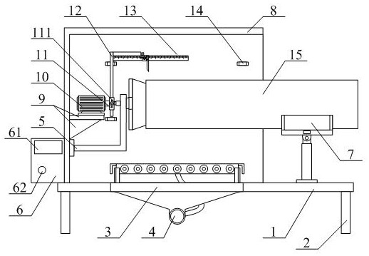
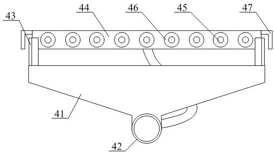
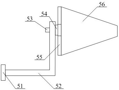
[0040] as attached figure 1 And attached figure 2 As shown, a cutting machine for anti-corrosion and thermal insulation pipe insulation foam layer with the function of collecting waste, including a workbench 1, support legs 2, installation groove 3, foam chip collection frame structure 4, pipe positioning frame structure 5, control box 6, Horizontal support frame structure 7, protective cover 8, mounting frame 9, angle motor 10, fixed pipe 11, vertical rod 12, knife rest fine-tuning mobile frame structure 13, hanging ring 14 and anti-corrosion insulation pipe 15, described support legs 2 respectively Welded at the four corners of the lower part of the workbench 1; the installation groove 3 is set on the inner side of the workbench 1; the foam chip collection frame structure 4 is arranged on the inner lower part of the workbench 1; the pipe positioning frame structure 5 Installed on the inner left side of the protective cover 8; the control box 6 is bolted to the lower left s...


PUM


Abstract

The invention provides a thermal insulation foam layer cutting machine with a scrap collecting function for an anti-corrosion thermal insulation pipeline. The cutting machine comprises a workbench, supporting legs, a mounting groove, a foam scrap collecting frame structure, a pipeline positioning frame structure, a control box, a horizontal supporting frame structure, a protective cover, a mounting frame, an angle motor, a fixing pipe, a vertical rod, a knife rest fine adjustment movable frame structure, a hanging ring and the anti-corrosion thermal insulation pipeline. The supporting legs arewelded at the four corners of the lower portion of the workbench respectively; the mounting groove is formed in the inner side of the workbench; and the foam scrap collecting frame structure is arranged on the inner side of the mounting groove. The device has the beneficial effects that through the arrangement of a collecting hopper and an external connecting pipe, an air suction pipe of an external dust collector is connected with the external connecting pipe through bolts, so that foam scraps generated during cutting of equipment can be collected, the situation that the foam scraps fall onto the ground and are inconvenient for workers to clean is prevented, and the cleaning effect of the equipment is improved.

Description

technical field [0001] The invention belongs to the technical field of cutting devices, and in particular relates to a cutting machine for an anti-corrosion and heat-preservation pipeline heat-insulation foam layer with the function of collecting waste. Background technique [0002] The outer wall of the pipe is wrapped with a layer of thermal insulation foam material to reduce the heat loss of the fluid in the pipeline and improve the heat transfer efficiency of the fluid. In order to facilitate the butt welding of different sections of pipes, the two ends of the anti-corrosion and heat preservation pipes are usually reserved when covering the insulation layer. [0003] However, the existing anti-corrosion and thermal insulation pipe insulation foam layer cutting machine with the function of collecting waste chips still has the disadvantages that the foam chips generated during cutting are not easy to clean, the pipeline cannot be positioned and the horizontality can not be...

Claims


Application Information

Patent Timeline
IPC IPC(8): B26D5/00B26D5/04B26D7/01B26D7/18B26D7/26B26D7/27
CPCB26D7/1863B26D7/27B26D5/005B26D7/01B26D5/04B26D7/2628B26D2007/013
Inventor 不公告发明人
Owner 河北君业科技股份有限公司
Learn More