
Device for detecting conveying stability of aerated concrete pouring mould box and bottom plate

A technology of aerated concrete and stability, applied in the direction of conveyor control devices, transportation and packaging, conveyors, etc., can solve the problems of no mold box in front, easy wear and tear of equipment, and unsmooth automatic production operation, so as to reduce equipment operation The effect of failure rate, increasing equipment service life, and reducing equipment maintenance time

Pending Publication Date: 2020-10-30
DONGYUE MACHINERY GRP
View PDF0 Cites 0 Cited by
  • Summary
  • Abstract
  • Description
  • Claims
  • Application Information

AI Technical Summary

Problems solved by technology

[0002] In production practice, it is found that due to the complex environment of the site, a lot of dust and oil, some products with hot steam, low transmission accuracy and easy wear and tear of the equipment, the mold box or the bottom plate is prone to undetectable or false detection during the transmission process. and so on
This makes the automatic production operation of the workshop not smooth enough, and it is prone to problems such as the rear mold box (bottom plate) hitting the front mold box (bottom plate), or there is no mold box (bottom plate) in the front, and the rear mold boxes (bottom plate) cannot automatically advance and line up.
Aiming at the above problems, we have tried proximity switch, photoelectric switch, travel switch and other methods successively. Due to the short detection distance of proximity switch, it is easy to fail to detect. Although the detection distance of photoelectric switch is long, it is easy to be interfered and cause false detection and is not good for dark colors. Sensitive, which makes the stability of the photoelectric switch detection cannot be guaranteed; the fixing screw of the stroke switch is easy to loosen when it is used in frequent collisions, and due to the short distance, it is easy to be damaged and has a high failure rate, so a detection method is now proposed Aerated Concrete Pouring Form Box and Base Plate Conveying Stability Device

Method used


Image

  • Device for detecting conveying stability of aerated concrete pouring mould box and bottom plate
  • Device for detecting conveying stability of aerated concrete pouring mould box and bottom plate
  • Device for detecting conveying stability of aerated concrete pouring mould box and bottom plate

Examples


Embodiment Construction

[0016] The following will clearly and completely describe the technical solutions in the embodiments of the present invention with reference to the accompanying drawings in the embodiments of the present invention. Obviously, the described embodiments are only some, not all, embodiments of the present invention.

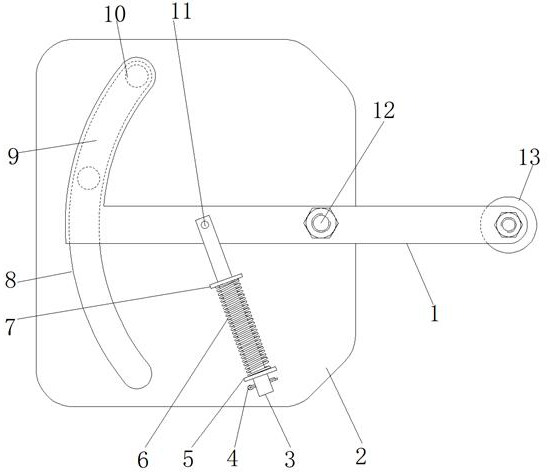
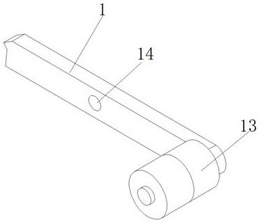
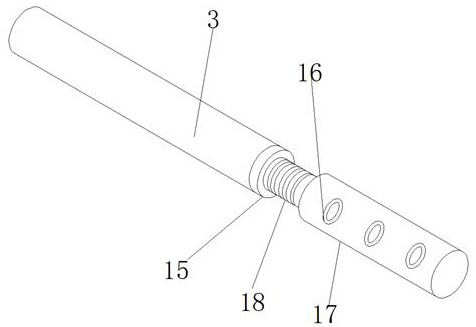
[0017] refer to Figure 1-3 , a device for detecting the transmission stability of the aerated concrete pouring mold box and the bottom plate, including a switch bracket bottom plate 2, a rotating shaft 12 is fixed on one side of the switch bracket bottom plate 2 through bolts, and the outer wall of the rotating shaft 12 is rotatably connected with a detection paddle 1 to detect One end of the plectrum 1 is provided with an arc-shaped bending part 9, and the side wall of the switch bracket bottom plate 2 is provided with an arc-shaped hole 8 near the position of the arc-shaped bending part 9, and the arc-shaped hole 8 is equipped with a proximity switch 10, and the ar...


PUM


Abstract

The invention discloses a device for detecting the conveying stability of an aerated concrete pouring mould box and a bottom plate. The device comprises a switch support bottom plate, one side of theswitch support bottom plate is fixed with a rotating shaft through a bolt, the outer wall of the rotating shaft is rotationally connected with a detection shifting piece, one end of the detection shifting piece is provided with an arc-shaped bending part, the side wall, close to the arc-shaped bending part, of the switch support bottom plate is provided with an arc-shaped hole, the arc-shaped holeis provided with a proximity switch, circular center positions of the arc-shaped hole and the arc-shaped bending part coincide with the position of the rotating shaft, a metal shaft is arranged at the side wall, close to the position between the rotating shaft and the arc-shaped bending part, of the detection shifting piece, a metal rod is rotationally connected to the outer wall of the metal shaft, and a first stop block is arranged on the outer wall of the metal rod. According to the device, unstable factors of a conventional detection method are well avoided, the equipment operation failure rate is greatly reduced, the equipment operation smoothness is improved, the automation integration level of a production system is improved, the equipment damage caused by faults in a workshop is reduced, and the equipment maintenance time is reduced.

Description

technical field [0001] The invention relates to the technical field of electrical detection of aerated concrete, in particular to a device for detecting the transmission stability of an aerated concrete pouring form box and a bottom plate. Background technique [0002] In production practice, it is found that due to the complex environment of the site, a lot of dust and oil, some products with hot steam, low transmission accuracy and easy wear and tear of the equipment, the mold box or the bottom plate is prone to undetectable or false detection during the transmission process. and so on. This makes the automatic production operation of the workshop not smooth enough, and it is prone to problems such as the rear mold box (bottom plate) hitting the front mold box (bottom plate), or there is no mold box (bottom plate) in the front, and the rear mold boxes (bottom plate) cannot automatically advance and line up. Aiming at the above problems, we have tried proximity switch, pho...

Claims


Application Information

Patent Timeline
Patent Type & Authority Applications(China)
IPC IPC(8): B65G43/08
CPCB65G43/08B65G2203/0208B65G2203/04
Inventor 孙京伟高兴鹏冯其坤陈阳
Owner DONGYUE MACHINERY GRP
Learn More