Integrated double-component injector, manufacturing method thereof and space equipment
An injector and bicomponent technology, applied in mechanical equipment, machines/engines, jet propulsion devices, etc., can solve the problems of low combustion efficiency of injectors and high manufacturing costs of integrated bicomponent injectors
- Summary
- Abstract
- Description
- Claims
- Application Information
AI Technical Summary
Problems solved by technology
Method used
Image

Examples
Embodiment 1
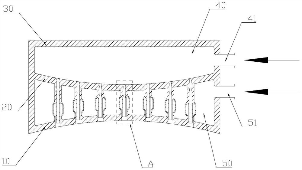
[0054] combine Figure 1-Figure 4 As shown, this embodiment provides an integrated two-component injector, including:
[0055] fuel chamber 50;
[0056] The first bottom surface 10 is arranged at the bottom of the fuel chamber 50;
[0057] The second bottom surface 20 is arranged on the top of the fuel chamber 50 and is opposite to the first bottom surface 10; and
[0058] At least one injection unit is communicated between the first bottom surface 10 and the second bottom surface 20;
[0059] Both the first bottom surface 10 and the second bottom surface 20 are curved surface structures.
[0060] Preferably, the fuel chamber 50 is configured as a closed or partially open cavity structure, the bottom and top of which are surrounded by the first bottom surface 10 and the second bottom surface 20 respectively, between the first bottom surface 10 and the second bottom surface 20. At least one injection unit is arranged between the second bottom surface 20, that is, the inject...
Embodiment 2
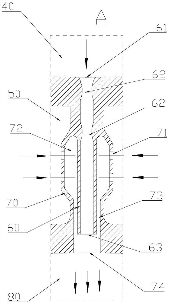
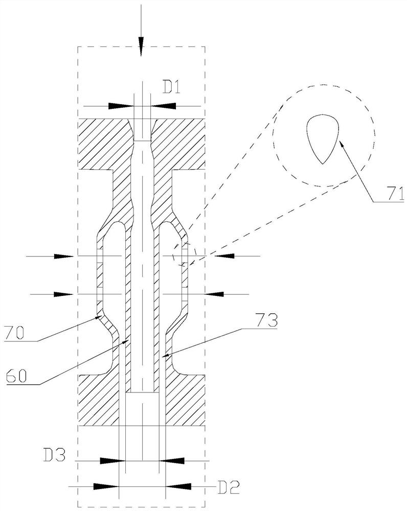
[0073] Based on the integrated dual-component injector described in the above embodiment, this embodiment introduces in detail the injection unit arranged inside the integrated dual-component injector.
[0074] Specifically, several injection units with different lengths are arranged between the first bottom surface 10 and the second bottom surface 20.
[0075] Since a plurality of injection units are arranged in the fuel chamber 50, the distribution form of the plurality of injection units in the fuel chamber 50 may be honeycomb distribution, checkerboard distribution, concentric circle distribution, etc. In addition, the structural form of the injection unit includes self-impact type, mutual impact type, coaxial direct current type, coaxial centrifugal type, etc. Preferably, in this embodiment, the injection unit adopts a coaxial straight-line injection unit.
[0076] This embodiment provides an integrated dual-component injector, and the injection units arranged between th...
Embodiment 3
[0093] This embodiment provides a method for manufacturing an integrated dual-component injector. The integrated dual-component injector described in Embodiment 1 and Embodiment 2 above is manufactured by 3D printing.
[0094] The manufacturing method of the integrated dual-component injector provided in this embodiment can reduce the development cost of the integrated dual-component injector and improve the production efficiency of the product by making the integrated dual-component injector through 3D printing , relying on 3D printing technology, the three-bottom two-cavity injector structure and hundreds of injection units are printed together in the form of an integral part, which greatly reduces the number of parts and reduces the product cost of the integrated two-component injector. cost; at the same time, the number of parts of the integrated dual-component injector is integrated from hundreds of pieces into one, which improves the production efficiency of the product, ...
PUM
| Property | Measurement | Unit |
|---|---|---|
| Granularity | aaaaa | aaaaa |
Abstract
Description
Claims
Application Information