
Semi-hermetic packaging device of optical device and semi-hermetic packaging process

A technology of hermetic packaging and packaging technology, which is applied to the sealing of engines, engine components, mechanical equipment, etc., which can solve the problems of repeated use of difficult-to-repair components, short working life of optical devices, and reduced work efficiency, so as to prevent water vapor condensation , low cost, and improved service life

Pending Publication Date: 2020-10-30
四川华拓光通信股份有限公司
View PDF0 Cites 0 Cited by
  • Summary
  • Abstract
  • Description
  • Claims
  • Application Information

AI Technical Summary

Problems solved by technology

Especially for components such as TEC, the erosion of water vapor will reduce its working efficiency or even damage it.
Disadvantages are: the welding method is used to seal the process. The material used for resistance welding is generally kovar metal. At the same time, the flatness of the base processing is relatively high. Secondly, the sealing and welding equipment and BOX\TO header are also more expensive, and the welding Difficult to rework and reuse components later
The disadvantage is that the air tightness is poor, and the internal air is easily condensed into water vapor attached to the surface of the components or glue due to temperature changes, causing damage to the components, resulting in short working life of the optical device

Method used


Image

  • Semi-hermetic packaging device of optical device and semi-hermetic packaging process
  • Semi-hermetic packaging device of optical device and semi-hermetic packaging process
  • Semi-hermetic packaging device of optical device and semi-hermetic packaging process

Examples


Embodiment Construction

[0046] The present invention will be further described in detail below in conjunction with the accompanying drawings, so that those skilled in the art can implement it with reference to the description.

[0047] It should be understood that terms such as "having", "comprising" and "including" as used herein do not entail the presence or addition of one or more other elements or combinations thereof.

[0048] It should be noted that in the description of the present invention, the orientation or positional relationship indicated by the term is based on the orientation or positional relationship shown in the drawings, which is only for the convenience of describing the present invention and simplifying the description, and does not indicate or imply No device or element must have a specific orientation, be constructed, and operate in a specific orientation and therefore should not be construed as limiting the invention. In addition, the terms "first" and "second" are used for de...


PUM


Abstract

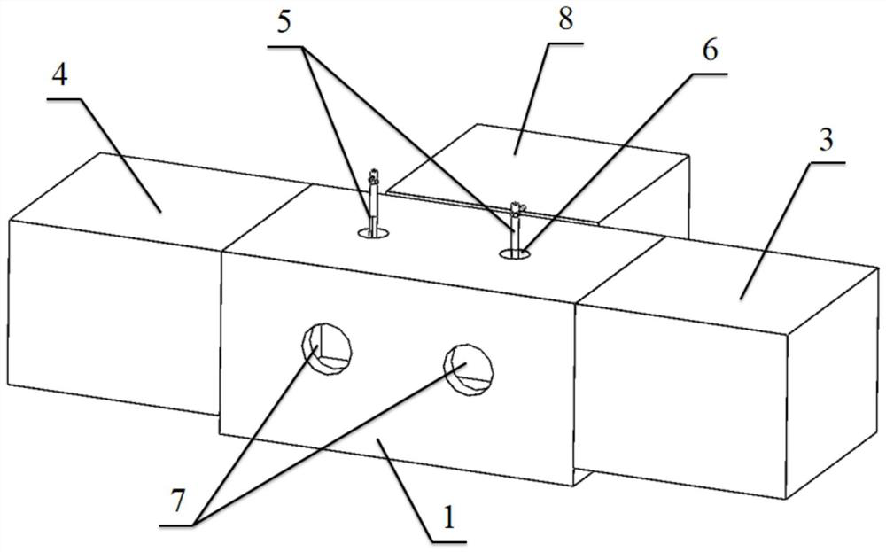
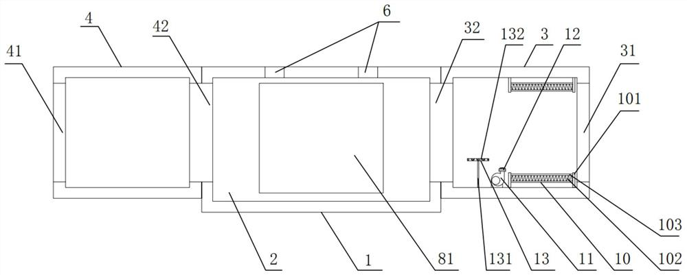
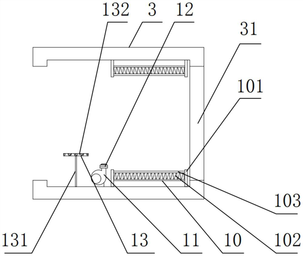
The invention discloses a semi-hermetic packaging device of an optical device and a semi-hermetic packaging process. The semi-hermetic packaging device comprises a main engine cabin, a first side cabin and a second side cabin. A center cabin is arranged in the main engine cabin. The first side cabin and the second side cabin are fixedly arranged on the two sides of the center cabin correspondingly. A first sealing door is arranged between the first side cabin and the center cabin, and a second sealing door is arranged between the second side cabin and the center cabin. An inlet sealing door isarranged on the side face of the first side cabin, and an outlet sealing door is arranged on the side face of the second side cabin. The main engine cabin and the center cabin are electrically connected. The main engine cabin is connected with an inert gas conveying device, and an inert gas conveying pipeline is connected between the main engine cabin and the center cabin. An upper end sealing opening is formed in the upper portion of the main engine cabin. A side face sealing opening is formed in the front portion of the center cabin. A heating device is mounted in the first side cabin. Thesemi-hermetic packaging device of the optical device and the semi-hermetic packaging process are easy to operate, water vapor can be effectively stopped from entering the optical device, and the service life of the optical device is prolonged.

Description

technical field [0001] The invention belongs to the technical field of optical communication device packaging, and more specifically, the invention relates to a semi-hermetic packaging device and a semi-hermetic packaging process for optical devices. Background technique [0002] At present, in the field of optical communication active optical devices, the packaging of active optical devices is divided into two ways, one is hermetic packaging and the other is non-hermetic packaging. The advantages and disadvantages of the two packaging methods are briefly described below. [0003] Hermetic packaging method: the closed space is filled with inert gas, and the sealed components are combined by resistance welding or other fusion welding methods. Such as TO package, BOX, and butterfly package, which are common in active optical device packages. According to the method 1014.10 in MIL-STD-883G, it is generally possible to achieve a leak rate of less than 5e-8atmcc / s for hermetica...

Claims


Application Information

Patent Timeline
IPC IPC(8): F16J15/02
CPCF16J15/02F16J15/022
Inventor 周情丁征卢浩
Owner 四川华拓光通信股份有限公司
Learn More