Integrated structure of evaporation tubes, evaporation tube type combustion chamber and miniature turbojet engine

A technology of evaporating tube and combustion chamber, which is applied in the direction of combustion chamber, continuous combustion chamber, machine/engine, etc., can solve the problems of temperature field difference at the outlet of combustion chamber, insufficient fuel atomization, large deviation of coaxiality, etc. Improve the coaxiality, enhance the effect of atomization and evaporation, and improve the effect of manufacturing compliance

Active Publication Date: 2020-10-30
AECC HUNAN AVIATION POWERPLANT RES INST
View PDF8 Cites 3 Cited by
  • Summary
  • Abstract
  • Description
  • Claims
  • Application Information

AI Technical Summary

Problems solved by technology

[0005] The invention provides an evaporating tube integrated structure, an evaporating tube type combustion chamber and a micro-turbojet engine to solve the problem of insufficient fuel atomization in the evaporating tube structure of the existing micro-turbojet engine, and a plurality of evaporating tubes welded to The technical problem of poor temperature field at the outlet of the combustion chamber due to large concentricity deviation on the support ring

Method used


Image

  • Integrated structure of evaporation tubes, evaporation tube type combustion chamber and miniature turbojet engine

Examples


Embodiment Construction

[0023] The embodiments of the present invention will be described in detail below with reference to the accompanying drawings, but the present invention can be implemented in various ways defined and covered below.

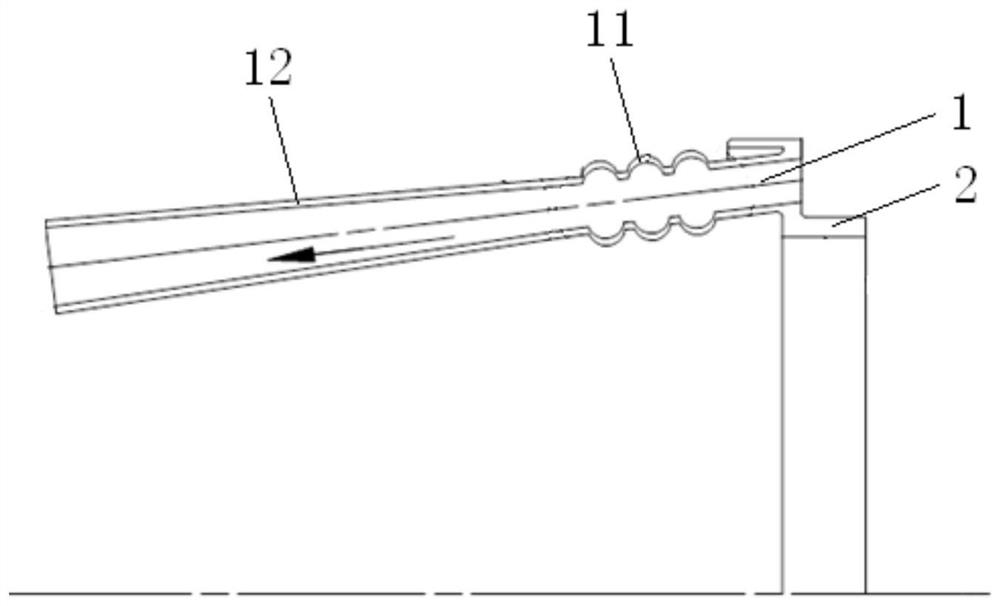
[0024] figure 1 It is a structural schematic diagram of the integrated structure of the evaporation tube in the preferred embodiment of the present invention.

[0025] Such as figure 1 As shown, the integrated structure of the evaporator tube in this embodiment is used to impact and mix the fuel sprayed by the fuel nozzle through the high-speed airflow to form a fuel-air mixture and spray it to the head area of ​​the combustion chamber. The evaporator tube is integrated The structure includes an evaporation tube 1 integrated with the support ring 2 of the combustion chamber. A plurality of evaporation tubes 1 are evenly arranged on the support ring 2 of the combustion chamber along the circumferential direction. The first end of the evaporation tube 1 is used for...


PUM


Abstract

The invention discloses an integrated structure of evaporation tubes, an evaporation tube type combustion chamber and a miniature turbojet engine. The integrated structure of the evaporation tubes isused to impact and mix fuel sprayed from fuel nozzles through high-speed airflow to form a fuel-air mixture and spray the fuel to the head area of the combustion chamber. The integrated structure of the evaporation tubes comprises a plurality of evaporation tubes integrated with a support ring of the combustion chamber, wherein the evaporation tubes are evenly arranged on the support ring of the combustion chamber in the circumferential direction, first ends of the evaporation tubes are inlet ends for inputting the high-speed airflow, second ends of the evaporation tubes are outlet ends for spraying the fuel-air mixture, the evaporation tubes comprise corrugated sections close to the inlet ends, the corrugated sections are provided with corrugated cavities protruding outwards in the radialdirections of the evaporation tubes, and the fuel nozzles are inserted from the outlet ends of the evaporation tubes into the corrugated sections of the evaporation tubes, so that the fuel sprayed from the fuel nozzles is impacted and mixed by the high-speed airflow in the corrugated sections to form the fuel-air mixture, and then the fuel is sprayed from the outlet ends of the evaporation tubesto the head area of the combustion chamber.

Description

technical field [0001] The invention relates to the technical field of micro-turbojet engines, in particular to an integrated structure of evaporating tubes, a combustion chamber of evaporating tubes and a micro-turbojet engine. Background technique [0002] The micro-turbojet engine has the characteristics of small size, light weight, simple structure, low cost, short life, easy maintenance and use, etc. It is widely used in military aviation or civilian aircraft model power devices such as unmanned aerial vehicles and loitering bombs. The micro-turbojet engine mostly adopts the evaporating tube combustion chamber, which has the advantages of simple structure, low manufacturing cost, and low oil supply pressure. The evaporator tube is an important part of the combustion chamber and is used to fully mix and atomize the fuel. [0003] The evaporator tube structure in the existing micro-turbojet engine, the evaporator tube is a pipe structure with equal cross-section and unif...

Claims


Application Information

Patent Timeline
Patent Type & Authority Applications(China)
IPC IPC(8): F23R3/32F02K3/00
CPCF23R3/32F02K3/00
Inventor 黄伟王梅娟汪玉明
Owner AECC HUNAN AVIATION POWERPLANT RES INST
Why Eureka
Try Eureka