Optical cage light beam generation system based on self-accelerating light beam

A technology of self-acceleration and light beams, applied in optics, optical components, instruments, etc., can solve the problems of cumbersome light cage beams and poor versatility

Active Publication Date: 2020-10-30
ZHEJIANG NORMAL UNIVERSITY
View PDF3 Cites 9 Cited by
  • Summary
  • Abstract
  • Description
  • Claims
  • Application Information

AI Technical Summary

Problems solved by technology

[0005] The embodiment of the present application provides a cage beam generation system based on a self-accelerating beam, to at least solve the problems of cumbersome cage beam generation and poor versatility in the cage beam generation system in the related art

Method used


Image

  • Optical cage light beam generation system based on self-accelerating light beam
  • Optical cage light beam generation system based on self-accelerating light beam
  • Optical cage light beam generation system based on self-accelerating light beam

Examples


Embodiment 1

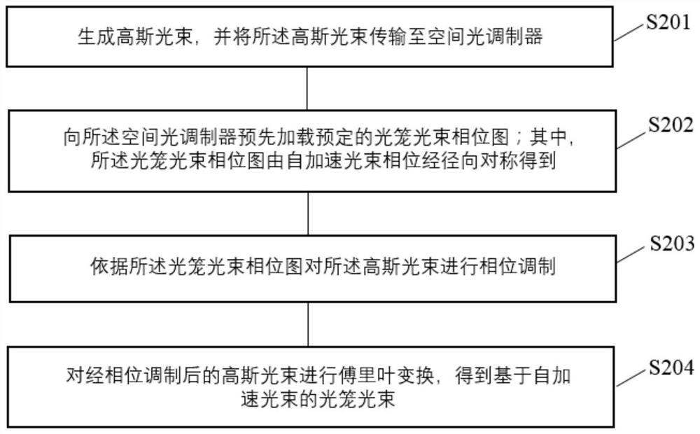
[0092] This embodiment provides a method for generating a cage beam based on a self-accelerating beam propagating along a fourth power trajectory, which mainly includes the following steps:

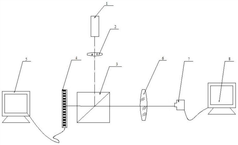
[0093] Step S201, generating a Gaussian beam and transmitting the Gaussian beam to the spatial light modulator 4;

[0094] Step S202, let the transmission track of the fourth power self-accelerating beam be: f(ξ)=a(ξ-b) 4 +c, through the mathematical model between the transmission trajectory and phase of the self-accelerating beam, the phase expression of the self-accelerating beam propagating along the fourth power trajectory is obtained as follows:

[0095]

[0096] Carrying out the radial symmetry operation on the above self-accelerating beam phase expression, the expression of the phase diagram of the cage beam is obtained as follows:

[0097]

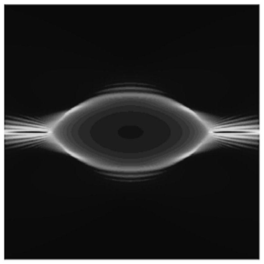
[0098] According to the above expression, take a=1 / 6000, b=30, c=-20, obtain the cage beam phase diagram through computer 5 design, an...

Embodiment 2

[0103] This embodiment provides a method for generating a cage beam based on a self-accelerating beam propagating along a half-period sinusoidal trajectory, which mainly includes the following steps:

[0104] Step S201, generating a Gaussian beam and transmitting the Gaussian beam to the spatial light modulator 4;

[0105] Step S202, let the transmission trajectory of the self-accelerating beam with a sinusoidal trajectory be recorded as f(ξ)=Asin(ωξ), and the phase expression of the self-accelerating beam propagating along the half-period sinusoidal trajectory is obtained through the mathematical model of the phase of the self-accelerating beam and its transmission trajectory:

[0106]

[0107] Among them, k 1 =k / (Aω), and -Aω≤k≤Aω is satisfied.

[0108] Carrying out the radial symmetry operation on the above self-accelerating beam phase expression, the cage beam phase expression is obtained as follows:

[0109]

[0110] Wherein, k1=kr / (Aω), and 0≤kr≤Aω is satisfied. ...


PUM


Abstract

The invention relates to an optical cage light beam generation system based on a self-accelerating light beam. The system comprises a Gaussian light emission unit, a computer, a spatial light modulator and a Fourier lens, wherein the Gaussian light emission unit is used for emitting a Gaussian light beam and transmitting the Gaussian light beam to the spatial light modulator; the computer is usedfor pre-loading a predetermined optical cage light beam phase diagram to the spatial light modulator; the optical cage light beam phase diagram is obtained by performing radial symmetry on a self-accelerating light beam phase; the spatial light modulator is positioned on a transmission light path of the Gaussian light beam and is used for carrying out phase modulation on the Gaussian light beam according to the optical cage light beam phase diagram; and the Fourier lens is used for carrying out Fourier transform on the Gaussian light beam subjected to phase modulation to obtain an optical cagelight beam based on the self-accelerating light beam. According to the optical cage light beam generation system, the one-dimensional self-accelerating light beam is changed into the circularly-symmetrical annular self-accelerating light beam in a radial symmetry mode, the optical cage light beam phase diagram is obtained, the system is simple and efficient, the requirement for the experimental environment is low, and more flexible optical capture can be achieved.

Description

technical field [0001] The present application relates to the technical field of beam control, in particular to a cage beam generation system based on a self-accelerating beam. Background technique [0002] Since the advent of laser technology, the high-intensity light source has made the mechanical effect of light move from theory to reality, and has been accurately verified and widely used in the laboratory. Optical tweezers technology has developed from this. The traditional optical tweezers are based on a three-dimensional optical potential well formed by converging Gaussian beams. The optical field distribution in the cross section is characterized by a large central energy and a gradual decrease in surrounding energy, so it is very suitable for trapping particles with high refractive index. However, for low refractive index particles Particles are difficult to capture. With the continuous development of laser technology, optical tweezers technology has begun to penetr...

Claims


Application Information

Patent Timeline
Patent Type & Authority Applications(China)
IPC IPC(8): G02B27/09G02B27/46
CPCG02B27/0927G02B27/0938G02B27/0905G02B27/46
Inventor 兰燕平钱义先
Owner ZHEJIANG NORMAL UNIVERSITY
Why Eureka
Try Eureka