Rectangular waveguide-based sweep frequency microwave imaging system based on matrix decomposition and detection method

A rectangular waveguide and microwave imaging technology, applied in the direction of using microwave flaw detection, etc., can solve the problems of multi-stage pump cavitation, affecting the service life of multi-stage pump, pump body breakdown, etc., to improve spatial resolution and realize real-time safety monitoring. , the effect of improving safety

Pending Publication Date: 2018-05-08
FUQING BRANCH OF FUJIAN NORMAL UNIV
View PDF4 Cites 7 Cited by
  • Summary
  • Abstract
  • Description
  • Claims
  • Application Information

AI Technical Summary

Problems solved by technology

[0009] When the near-field effect imaging device for internal steel structure corrosion damage of the cable is running, since the engine drives the pump wheel to rotate at a high speed, high-pressure and high-speed water flows from the inner side of the pump wheel to the outer edge to form a high-pressure and high-speed water flow that impacts the turbine, thus easily causing multi-stage pump cavitation Phenomenon, causing the pump body to be broken down, affecting the service life of the multi-stage pump

Method used


Image

  • Rectangular waveguide-based sweep frequency microwave imaging system based on matrix decomposition and detection method
  • Rectangular waveguide-based sweep frequency microwave imaging system based on matrix decomposition and detection method
  • Rectangular waveguide-based sweep frequency microwave imaging system based on matrix decomposition and detection method

Examples


Embodiment Construction

[0045] The present invention will be described in detail below in conjunction with the accompanying drawings and specific embodiments.

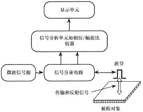
[0046] Such as figure 1 As shown, a waveguide based sweep frequency microwave (WSFM) imaging system based on matrix decomposition includes a computer, a display unit, an XYZ displacement mechanism, a directional signal beam splitting circuit, a signal analysis unit, a microwave signal source and a waveguide, etc. . The waveguide includes a rectangular waveguide and a detection unit, which is an important part of the waveguide microwave detection system. The rectangular waveguide can be configured as a single waveguide or as a double waveguide. The single waveguide can use the detector to acquire the signal, and also can use the same waveguide to realize the transmitting and collecting functions. Dual waveguides can be configured as reflective or transmissive.

[0047] A typical reflective waveguide microwave detection system such as figu...


PUM


Abstract

The invention relates to a rectangular waveguide-based sweep frequency microwave imaging system based on matrix decomposition. The rectangular waveguide-based sweep frequency microwave imaging systemcomprises a computer, a display unit, an XYZ displacement mechanism, a directional signal beam splitting circuit, a signal analysis unit, a microwave signal source and a waveguide, wherein the computer is connected with the XYZ displacement mechanism by a serial port, controls the XYZ displacement mechanism to move the waveguide and executes data acquiring and processing; the display unit displaysa final detection result image; the XYZ displacement mechanism moves the rectangular waveguide or a detected object, realizes control over the detection distance between the waveguide and the detected object and acquires detection data; the directional signal beam splitting circuit separates and directs part of a transmission signal and a reflection signal; the waveguide is a rectangular openingwaveguide and realizes transmitting and acquiring functions of a microwave signal; the signal analysis unit is a vector network analyzer and realizes measurement of microwave signal amplitude and phase; the microwave signal source transmits the microwave signal to the waveguide by the directional signal beam splitting circuit; the waveguide is connected with the signal analysis unit by a coaxial cable; and the computer is connected with the signal analysis unit by a general purpose interface bus (GBIP).

Description

technical field [0001] The invention relates to a rectangular waveguide microwave imaging system and a detection method thereof, in particular to a rectangular waveguide frequency-sweeping microwave imaging system and a detection method based on matrix decomposition, and belongs to the technical fields of nondestructive detection, medical imaging and target detection. Background technique [0002] The principle of microwave imaging detection technology is to comprehensively study the interaction between microwave and the measured object. On the one hand, microwaves will produce reflection, scattering, and transmission at discontinuous interfaces to realize the detection of the surface and subsurface of the measured material; on the other hand, microwave It will also interact with the material to be tested. At this time, the microwave signal will be affected by the electromagnetic parameters and geometric parameters in the material, so as to realize the detection of the physic...

Claims


Application Information

Patent Timeline
Patent Type & Authority Applications(China)
IPC IPC(8): G01N22/02
CPCG01N22/02
Inventor 张宏吴瑞坤徐鲁雄严明忠张荣刚陈国钦李金赐
Owner FUQING BRANCH OF FUJIAN NORMAL UNIV
Why Eureka
Try Eureka