
Fixed bar code scanner based on Internet of Things

A barcode scanner, a fixed technology, applied in the field of scanners, which can solve the problems of wasted labor, affecting the progress of scanning, and the scanner being unable to prepare to scan barcodes.

Inactive Publication Date: 2020-10-30
广州心蛙科技有限责任公司
View PDF0 Cites 0 Cited by
  • Summary
  • Abstract
  • Description
  • Claims
  • Application Information

AI Technical Summary

Problems solved by technology

[0003] In the process of barcode scanning by modern fixed barcode scanners, because the staff scans too fast, the scanner cannot quickly scan the barcodes, and the equipment cannot send signals to the unscanned barcodes, and the staff cannot accurately distinguish them, resulting in scanning errors. The quality cannot be guaranteed, and the problem of property waste. At the same time, due to the dark outside light during scanning, the scanner cannot prepare to scan the barcode. It takes a lot of time for workers to align the barcode with the scanner, which affects the scanning progress and results in low scanning efficiency. , the problem of wasting time, and because the scanner is fixed on the desktop, it is inconvenient to take it off. When the scanner is damaged, it will take a lot of labor to disassemble it, which will affect the progress of maintenance, resulting in difficulty in maintenance and waste of labor. Now we introduce a A fixed barcode scanner based on the Internet of Things

Method used


Image

  • Fixed bar code scanner based on Internet of Things
  • Fixed bar code scanner based on Internet of Things
  • Fixed bar code scanner based on Internet of Things

Examples


Embodiment Construction

[0035] The following will clearly and completely describe the technical solutions in the embodiments of the present invention with reference to the accompanying drawings in the embodiments of the present invention. Obviously, the described embodiments are only some, not all, embodiments of the present invention. Based on the embodiments of the present invention, all other embodiments obtained by persons of ordinary skill in the art without making creative efforts belong to the protection scope of the present invention.

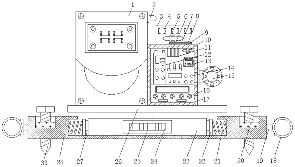
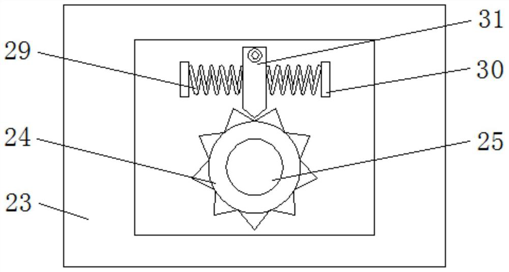
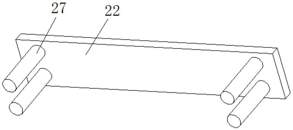
[0036] see Figure 1-5, a fixed barcode scanner based on the Internet of Things, including a scanner body 1, an alarm 2 is fixedly connected to the top of the right side of the scanner body 1, and a chassis 17 is fixedly connected to the right side of the scanner body 1, and the chassis 17 The bottom surface of the inner cavity is fixedly connected with a processor 16, the left side of the top surface of the processor 16 is fixedly connected with a transmitter...


PUM


Abstract

The invention relates to the technical field of scanners, and discloses a fixed bar code scanner based on the Internet of Things. The bar code scanner comprises a scanner body, the top end of the right side of the scanner body is fixedly connected with an alarm, the right side of the scanner body is fixedly connected with a case, the bottom surface of an inner cavity of the case is fixedly connected with a processor, and the left side of the top surface of the processor is fixedly connected with an emitter. Signals of the light source and the receiver are received through the processor for comparison; when the light source emits a signal and the receiver does not receive the signal, the processor processes the signals and sends the signals to the emitter; the emitter drives the alarm to give an alarm and transmits a signal to a communicator at the same time; the communicator transmits a non-scanned signal to the computer terminal, so the problems that the scanning speed of workers is too high, a scanner cannot quickly scan bar codes, equipment cannot send signals to the non-scanned bar codes, the workers cannot accurately distinguish the non-scanned bar codes, the scanning qualitycannot be guaranteed, and property waste is caused are solved.

Description

technical field [0001] The invention relates to the technical field of scanners, in particular to a fixed barcode scanner based on the Internet of Things. Background technique [0002] Barcode scanner, also known as barcode reader, barcode scanning gun, barcode scanner, barcode scanning gun and barcode reader, is a reading device used to read the information contained in the barcode, using optical principles to decode the content of the barcode After that, it is transmitted to a computer or other equipment through a data line or wirelessly. It is widely used in supermarkets, logistics express, libraries, etc. to scan the barcodes of commodities and documents. The structure of the barcode scanner is divided into several parts: light source, receiving device, photoelectric Conversion parts, decoding circuit, computer interface, laser scanner scanning window light-transmitting mirror is made of special tempered material, the light transmittance is smooth, the depth of field is ...

Claims


Application Information

Patent Timeline
IPC IPC(8): G06K7/14
CPCG06K7/1408G06K7/1465
Inventor 龙亚梅
Owner 广州心蛙科技有限责任公司
Learn More