Pneumatic endoscope anastomat

A stapler and laparoscopic technology, applied in the field of laparoscopic staplers, can solve problems such as complex structures

Pending Publication Date: 2020-11-03
江苏越众医疗科技有限公司
View PDF7 Cites 2 Cited by
  • Summary
  • Abstract
  • Description
  • Claims
  • Application Information

AI Technical Summary

Problems solved by technology

For example, the Chinese patent document "CN101313865A" with the publication number "Pneumatic Surgical Cutting and Fastening Instrument with Electric Control and Recording Mechanism" discloses power assistance through pneumatic drive components; The motor-driven surgical cutting instrument of the device orientation control assembly" discloses that the auxiliary power is provided by the motor, but the structure is slightly complicated

Method used


Image

  • Pneumatic endoscope anastomat
  • Pneumatic endoscope anastomat
  • Pneumatic endoscope anastomat

Examples


Embodiment Construction

[0044] The technical solutions of the present invention will be clearly and completely described below in conjunction with the accompanying drawings. Apparently, the described embodiments are some of the embodiments of the present invention, but not all of them. Based on the embodiments of the present invention, all other embodiments obtained by persons of ordinary skill in the art without making creative efforts belong to the protection scope of the present invention.

[0045] In the description of the present invention, it should be noted that the terms "center", "upper", "lower", "left", "right", "vertical", "horizontal", "inner", "outer" etc. The indicated orientation or positional relationship is based on the orientation or positional relationship shown in the drawings, and is only for the convenience of describing the present invention and simplifying the description, rather than indicating or implying that the referred device or element must have a specific orientation, ...


PUM


Abstract

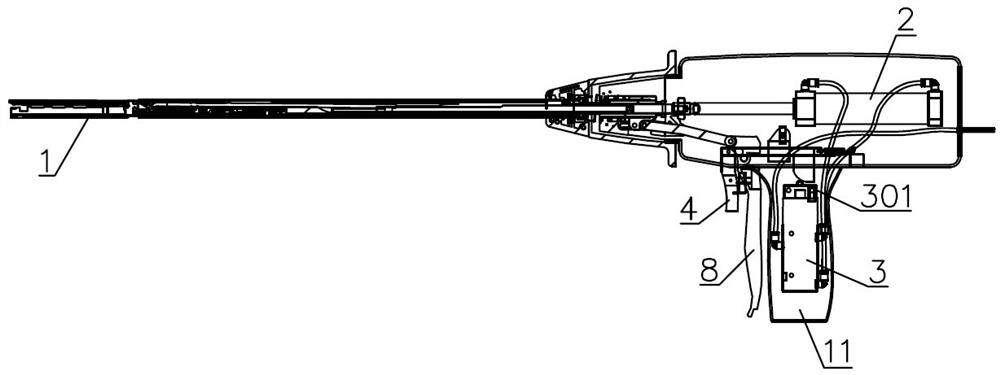
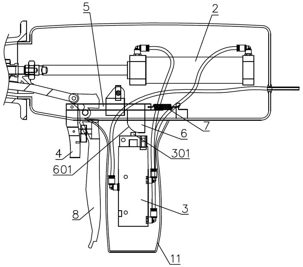
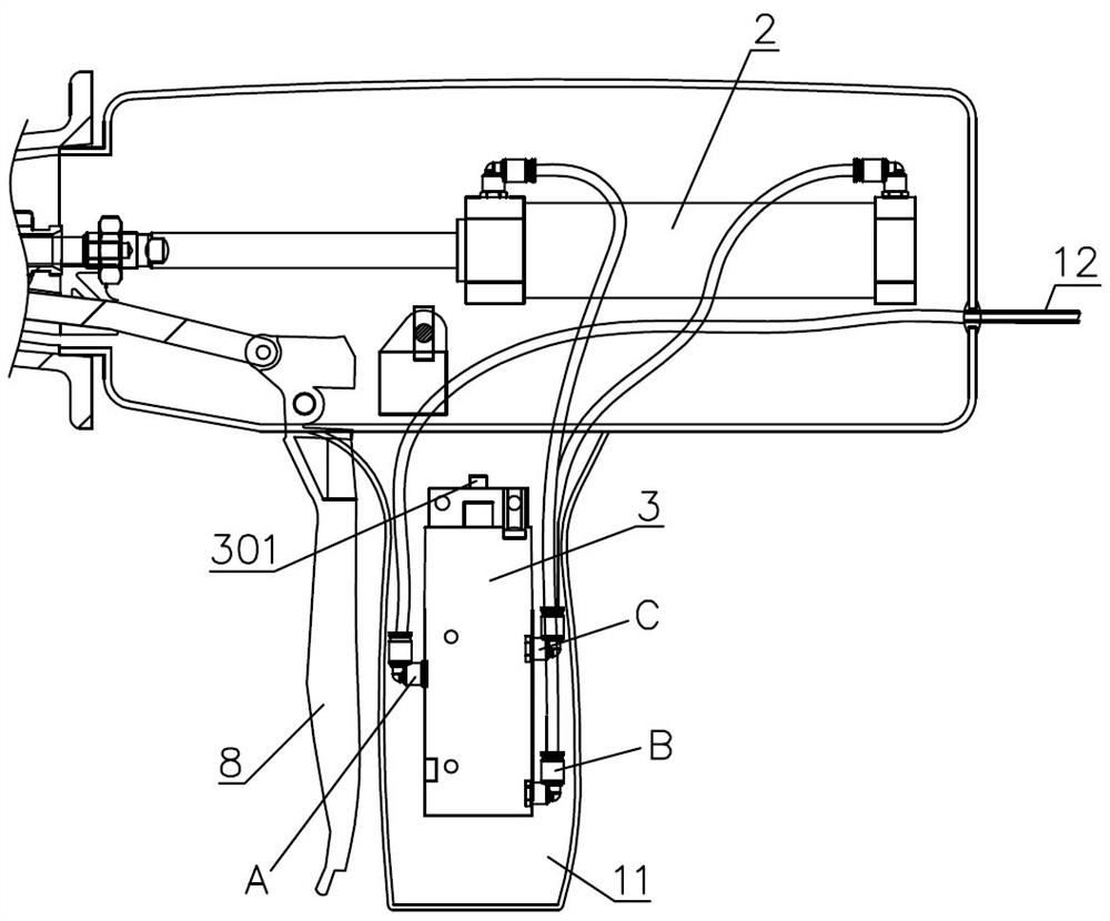
The invention relates to a pneumatic endoscope anastomat. The pneumatic endoscope anastomat comprises an executing head, an air cylinder, a manual control valve and a control wrench, wherein the executing head is used for cutting and suturing soft tissue; the driving end of the air cylinder is connected to the executing head; the manual control valve is connected to the air cylinder and is used for switching the flow direction of air flow communicating with the air cylinder; and the control wrench is arranged corresponding to the manual control valve and is used for controlling the manual control valve. Due to the fact that the executing head, the air cylinder, the manual control valve and the control wrench are arranged, after the air cylinder is connected with an air source, the manual control valve can be triggered through the control wrench, the air source in the air cylinder switches the flow direction, the driving end of the air cylinder is controlled to move forwards or backwards, and air cylinder actions are transmitted to the executing head to provide power for blade cutting and anastomotic nail discharging and suturing. After execution, the air flow direction of the air cylinder can be switched, and the driving end of the air cylinder retreats. The pneumatic endoscope anastomat is simple in structure and easy to control.

Description

technical field [0001] The invention relates to a laparoscopic stapler, in particular to a pneumatic laparoscopic stapler. Background technique [0002] Laparoscopic staplers, such as medical linear cutting staplers, are used for cutting soft tissues and suturing the edges of the opposite sides of the incision in laparoscopic surgery. Its executive head is equipped with a staple cartridge, anvil and blade, and the operation is mostly manual operation. The corresponding button or wrench is pushed by the surgeon's hand to provide power for the blade to move forward and the staple cartridge seat used to push out the staples. [0003] If the auxiliary drive mechanism can be used to provide power for blade cutting and staple ejection, the doctor's labor can be reduced, which is conducive to reducing operation time and improving operation quality. For example, the Chinese patent document "CN101313865A" with the publication number "Pneumatic Surgical Cutting and Fastening Instrume...

Claims


Application Information

Patent Timeline
Patent Type & Authority Applications(China)
IPC IPC(8): A61B17/068A61B17/072A61B17/94
CPCA61B17/068A61B17/07207A61B17/00234A61B2017/00544
Inventor 刘成
Owner 江苏越众医疗科技有限公司
Why Eureka
Try Eureka