
Drum-type leftover material recovery device for non-woven fabric production

A recycling device and drum-type technology, applied in the field of drum-type scrap recycling devices for non-woven production, can solve the problems of low crushing efficiency and poor effect of non-woven fabrics, improve product quality and work efficiency, and achieve good crushing effect. The effect of meeting recycling needs

Inactive Publication Date: 2020-11-03
叶能
View PDF9 Cites 2 Cited by
  • Summary
  • Abstract
  • Description
  • Claims
  • Application Information

AI Technical Summary

Problems solved by technology

[0005] The purpose of the present invention is to solve the problems of low crushing efficiency and poor effect of the above-mentioned non-woven fabrics, and provide a drum-type scrap recovery device for non-woven fabrics with high efficiency and good crushing effect

Method used


Image

  • Drum-type leftover material recovery device for non-woven fabric production
  • Drum-type leftover material recovery device for non-woven fabric production
  • Drum-type leftover material recovery device for non-woven fabric production

Examples


Embodiment 1

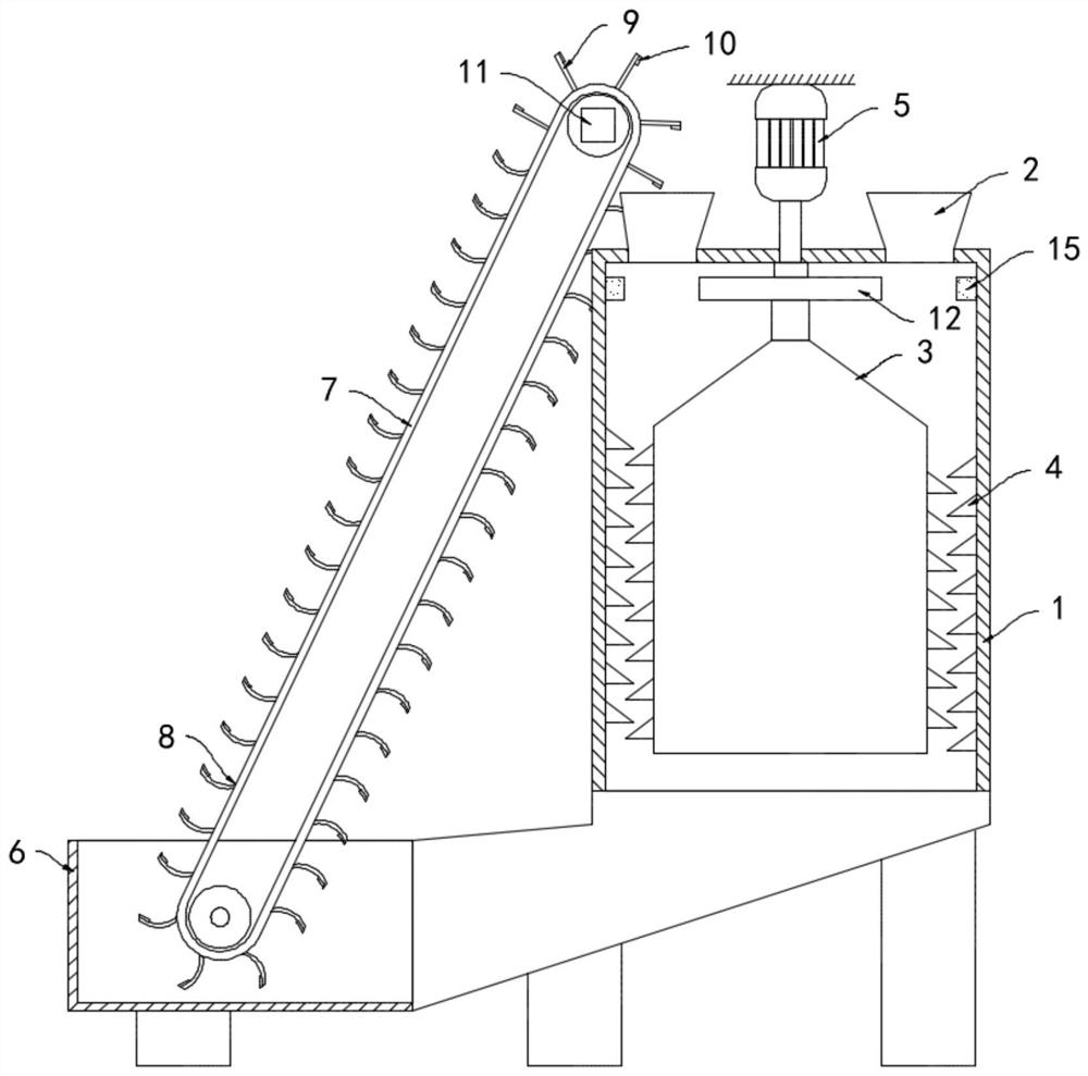
[0019] like Figure 1-3 As shown, a drum-type scrap recovery device for non-woven fabric production includes a cylindrical shell 1, the upper end of the cylindrical shell 1 is provided with a feeding port 2, and a crushing device is arranged inside the cylindrical shell 1 along its axial direction. Tube 3, the outer wall of the crushing tube 3 and the inner wall of the cylindrical shell 1 are equidistantly equipped with a plurality of crushing blades 4, and the plurality of crushing blades 4 are spirally arranged in a staggered manner, and the non-woven fabric can be crushed during the rotation and crushing process. Push down.

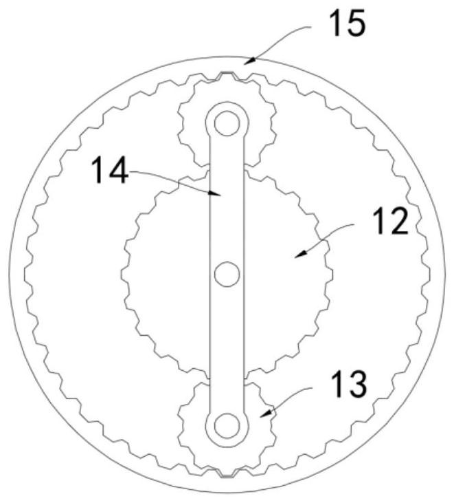
[0020] A driving motor 5 is arranged above the cylindrical housing 1, and the driving motor 5 is connected with the crushing cylinder 3 through a driving mechanism. Coaxially fixed, the outer ring of the driving gear 12 is meshed with two planetary gears 13, the upper end of the planetary gear 13 is connected to the rotating shaft along its axis, and ...

Embodiment 2

[0026] like Figure 4 As shown, the difference between this embodiment and Embodiment 1 is that an air chamber 16 is provided in the crushing cylinder 3, an air inlet is provided at the upper end of the air chamber 16, and a fan 17 is coaxially installed on the inner wall of the air chamber 16. , The top surface of the air cavity 16 is installed with a helically wound conductive coil 18 , and the inner wall of the cylindrical housing 1 is installed with a ring magnet 19 .

[0027] In this embodiment, when the crushing cylinder 3 rotates, it drives the conductive coil 18 and the fan 17 to rotate. According to the principle of electromagnetic induction, when the magnetic flux in the closed coil changes, an induced current will be generated in the closed coil, and the conductive coil 18 will generate an induced current. Induction current is generated, electric energy is converted into heat energy to generate heat, no external power supply is needed, and the problem of external wi...


PUM


Abstract

The invention belongs to the technical field of non-woven fabric production, and particularly relates to a drum-type leftover material recovery device for non-woven fabric production. The drum-type leftover material recovery device comprises a cylindrical shell, a feeding hole is formed in the upper end of the cylindrical shell, and a crushing drum is arranged in the cylindrical shell in the axisdirection of the cylindrical shell; a plurality of crushing blades are installed on the outer side wall of the crushing drum and the inner side wall of the cylindrical shell at equal intervals, the multiple crushing blades are spirally arranged in a staggered manner, a driving motor is arranged above the cylindrical shell and connected with the crushing drum through a driving mechanism, and a collecting groove is rotatably connected to the bottom of the cylindrical shell; and a conveying belt is arranged in the collecting groove. By means of relative rotation of the crushing drum and the cylindrical shell, non-woven fabric is cut and crushed, the crushing effect is better, crushed non-woven fabric fragments can be screened and cut multiple times, the recycling requirement of the non-wovenfabric is met, a crushing device does not need to be adjusted or replaced, and the product quality and the working efficiency are greatly improved.

Description

technical field [0001] The invention belongs to the technical field of non-woven fabric production, and in particular relates to a drum-type scrap recycling device for non-woven fabric production. Background technique [0002] Non-woven fabrics are composed of directional or random fibers. They have the advantages of moisture resistance, breathability, rich colors, and recyclability. They are widely used in people's production and life. The leftover materials are cut off, collected, crushed and recycled by the crusher, so as to improve resource utilization and reduce production costs. [0003] The traditional non-woven fabric crusher is extruded by two crushing rollers, and the non-woven fabric is cut and crushed by the hob on the surface of the crushing roller. The specifications of the crushed materials are inconsistent, and it is difficult to meet the needs of recycling. It is necessary to constantly replace and adjust the gap between the two crushing rollers to adapt to...

Claims


Application Information

Patent Timeline
Patent Type & Authority Applications(China)
IPC IPC(8): B02C18/06B02C18/10B02C18/16B02C18/18B02C18/24B02C23/12B02C23/28B02C19/18
CPCB02C18/0084B02C18/067B02C18/10B02C18/16B02C18/18B02C18/24B02C19/186B02C23/12B02C23/28
Inventor 叶能
Owner 叶能
Learn More