Garbage air separation system
A garbage and winnowing technology, which is applied in the direction of solid separation, separating solids from solids with airflow, chemical instruments and methods, etc., can solve the problems of poor applicability, affecting the separation degree of light garbage and heavy garbage, and the inability to adjust light garbage. The problem of the separation degree of high-quality waste and heavy waste, etc., to achieve the effect of good separation
- Summary
- Abstract
- Description
- Claims
- Application Information
AI Technical Summary
Problems solved by technology
Method used
Image

Examples
Embodiment 1
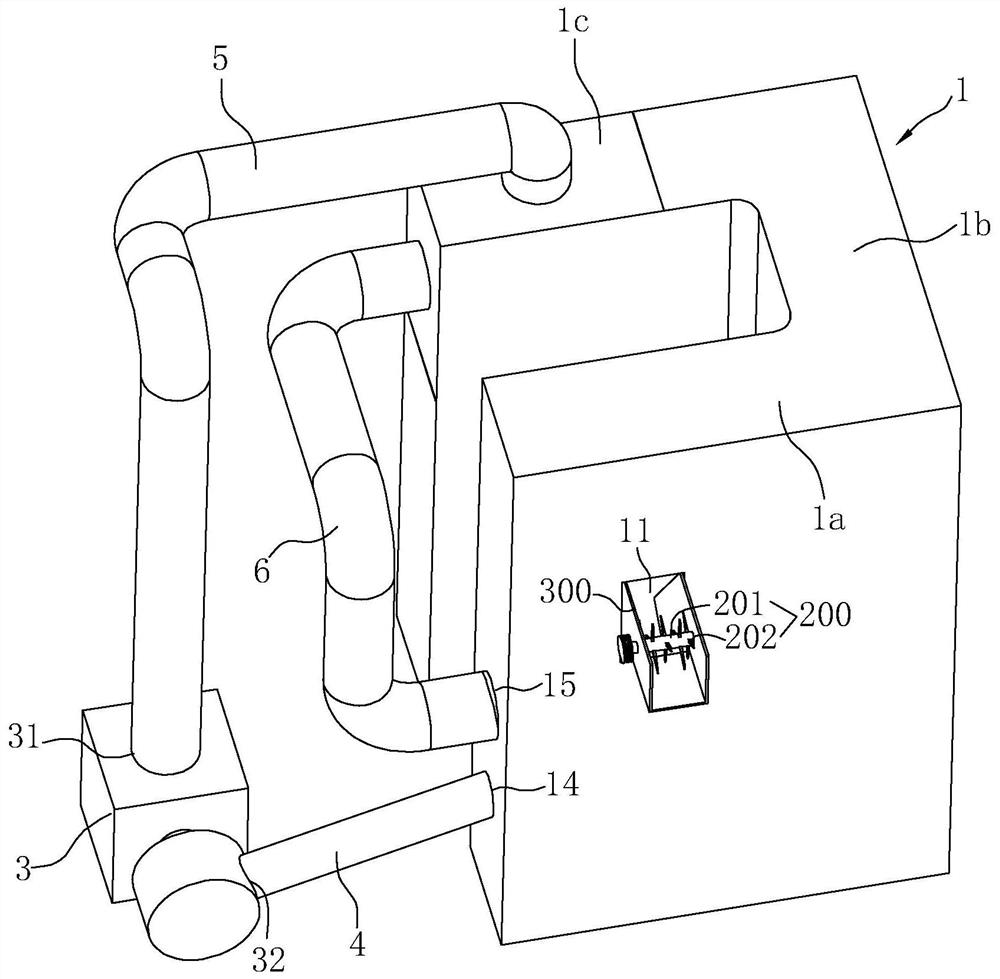
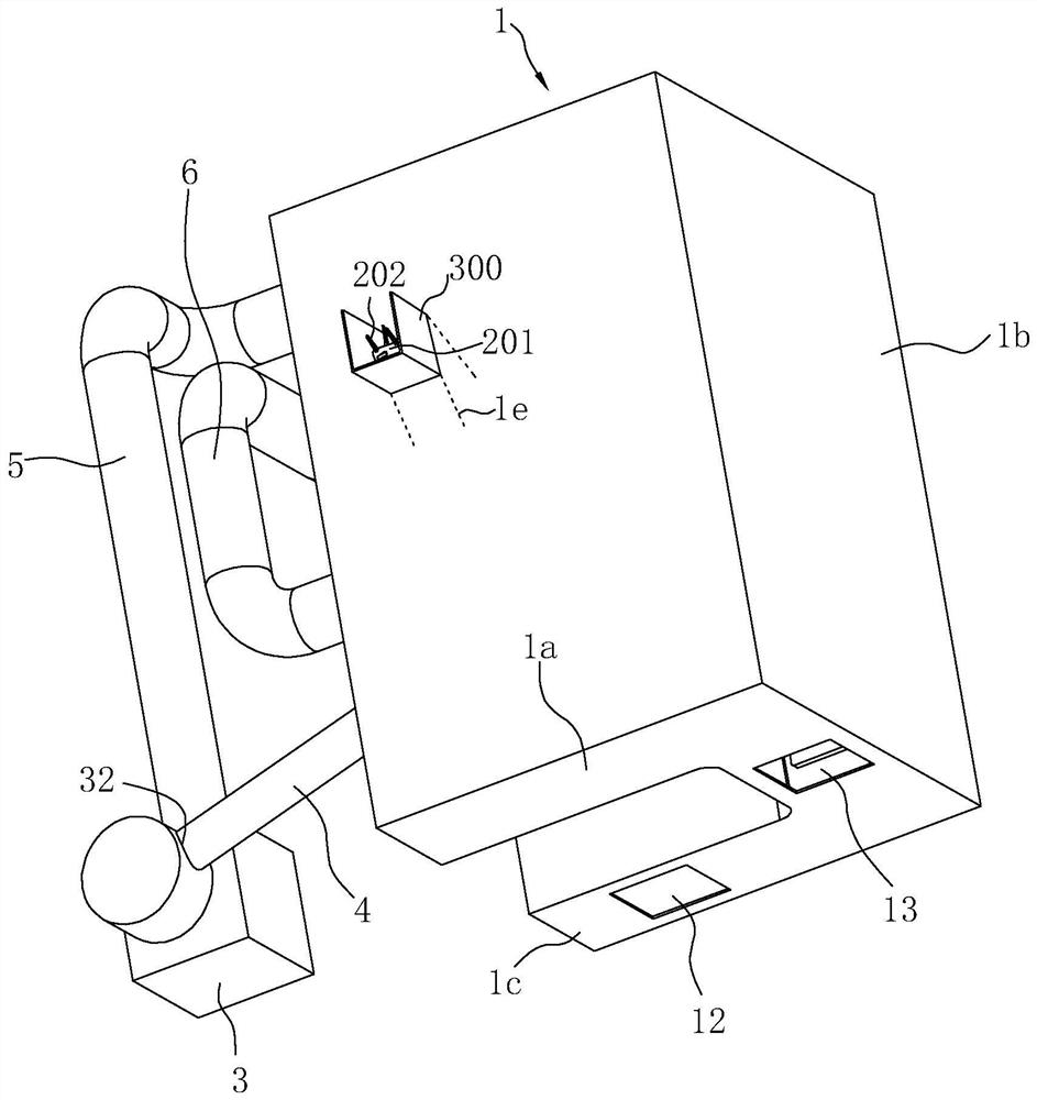
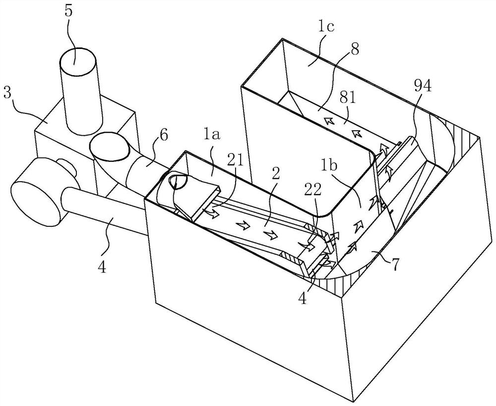
[0070] Such as Figure 1 to Figure 11 Shown is a preferred embodiment of the present invention.
[0071] The garbage winnowing system includes winnowing room 1, conveyor belt 2, blower fan 3, air outlet duct 4, first return air duct 5, second return air duct 6, heavy garbage hopper 7, light garbage hopper 8, screen 100, a splitter device 9, a toggle device 200, a feed channel 300, a geared motor (not shown in the figure) and the like.
[0072] Wherein, the feed channel 300 communicates with the feed port 11 .
[0073] The winnowing chamber 1 has a hollow inner cavity, a feed port 11 communicating with the hollow inner cavity, a light garbage outlet 12, a heavy garbage outlet 13, a first air inlet 14, a second air inlet 15, and a first return air outlet 16. With the second air return port 17, the feed port 11 is positioned at the sidewall of the winnowing chamber 1 and is provided with a guide passage 1e at the feed port 11 (referring to figure 2 , Figure 10 , Figure 11...
Embodiment 2
[0101] see Figure 12 ~ Figure 13 , and the structure of embodiment 1 is basically the same, the difference is: the cross-section of winnowing chamber 1 is hollow Z-shaped.
[0102] Working principle and using method are the same as embodiment 1.
PUM
 Abstract
Description
Claims
Application Information
 - R&D
- Intellectual Property
- Life Sciences
- Materials
- Tech Scout
- Unparalleled Data Quality
- Higher Quality Content
- 60% Fewer Hallucinations
Browse by: Latest US Patents, China's latest patents, Technical Efficacy Thesaurus, Application Domain, Technology Topic, Popular Technical Reports.
© 2025 PatSnap. All rights reserved.Legal|Privacy policy|Modern Slavery Act Transparency Statement|Sitemap|About US| Contact US: help@patsnap.com