Metal pipeline spiral part rust removal device

A metal pipe and helix technology, which is applied in the field of metal pipe helix derusting devices, can solve problems such as affecting subsequent use, difficulty in screwing metal pipes, and incomplete derusting of the helix of metal pipes, etc., so as to improve the effect and efficiency Effect

Active Publication Date: 2020-11-03
山东通洁科技工程有限公司
View PDF10 Cites 4 Cited by
  • Summary
  • Abstract
  • Description
  • Claims
  • Application Information

AI Technical Summary

Problems solved by technology

[0005] In order to overcome the shortcomings that although the surface of the metal pipe can be derusted, the derusting of the spiral part of the metal pipe is not complete, which makes the metal pipe difficult to screw and affects the subsequent use. The technical problem to be solved is: to provide a metal The spiral part of the pipe is fully derusted, which does not affect the metal pipe spiral part derusting device for subsequent use of the metal pipe

Method used


Image

  • Metal pipeline spiral part rust removal device
  • Metal pipeline spiral part rust removal device
  • Metal pipeline spiral part rust removal device

Examples


Embodiment 1

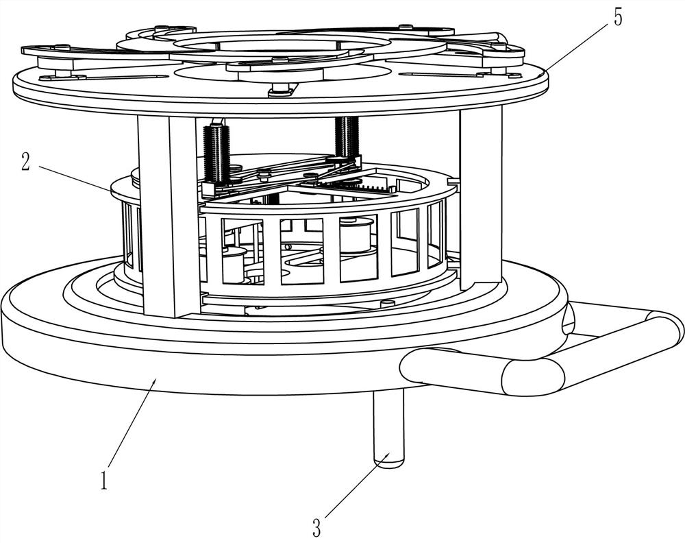
[0028] refer to Figure 1-Figure 6 , a metal pipe spiral part derusting device, including a ring base 1, a rotating frame 2, a rocker 3, a derusting mechanism 4 and a fixing mechanism 5, and the rotating connection between the inner lower parts of the three pillars of the ring base 1 There is a rotating frame 2, the upper part of the rotating frame 2 is provided with a derusting mechanism 4, the top of the ring base 1 is provided with a fixing mechanism 5, and the eccentric position of the outer bottom of the rotating frame 2 is fixedly connected with a rocking handle 3.

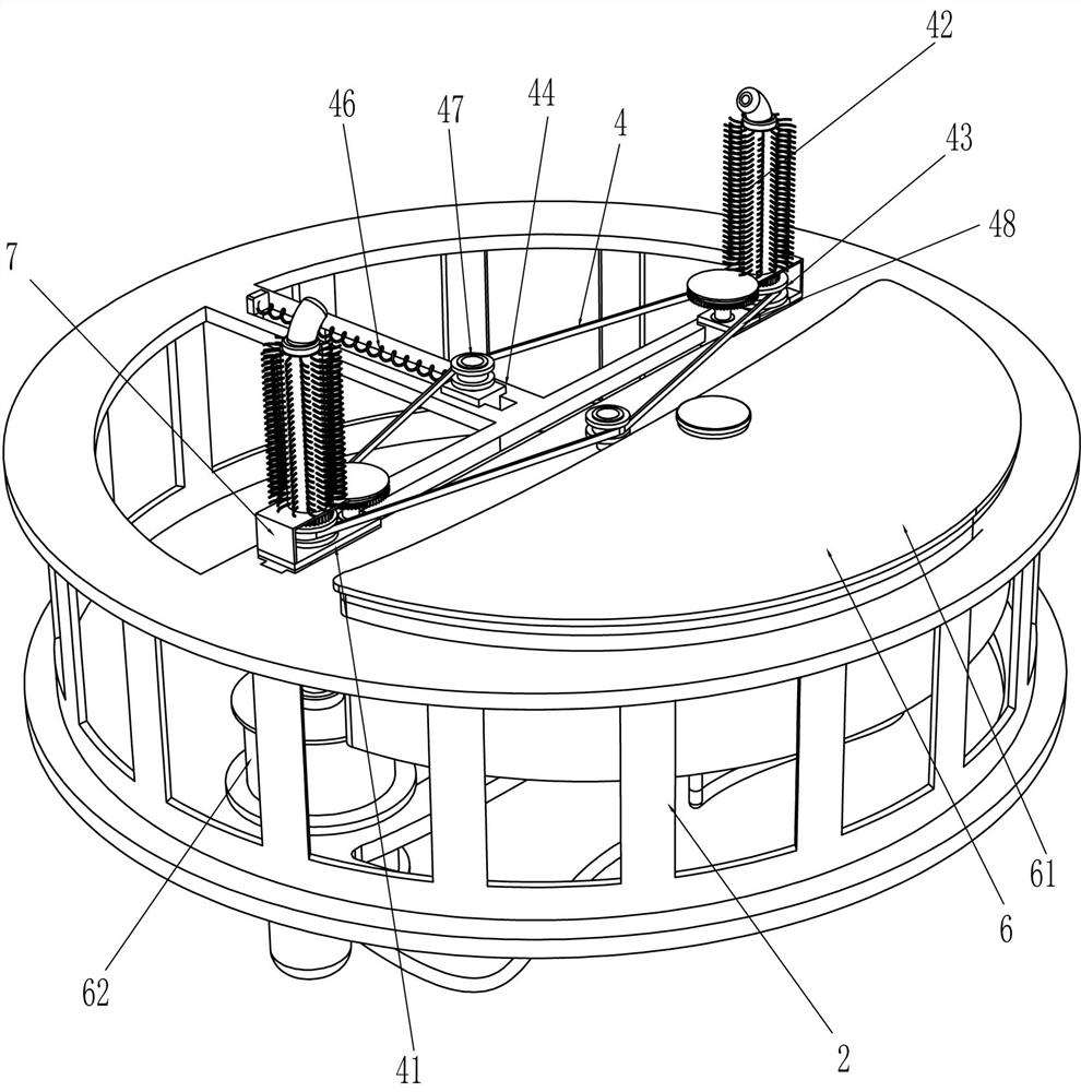
[0029]Derusting mechanism 4 comprises horizontal slide block 41, derusting pipe 42, belt pulley 43, guide slider 44, drive motor 45, extension spring 46, guide wheel 47 and drive belt 48, the design of slide type in the middle of rotating frame 2 tops There are two horizontal sliders 41, the top of the horizontal slider 41 is rotatably connected with a derusting pipe 42, and the outside of the lower part of ...

Embodiment 2

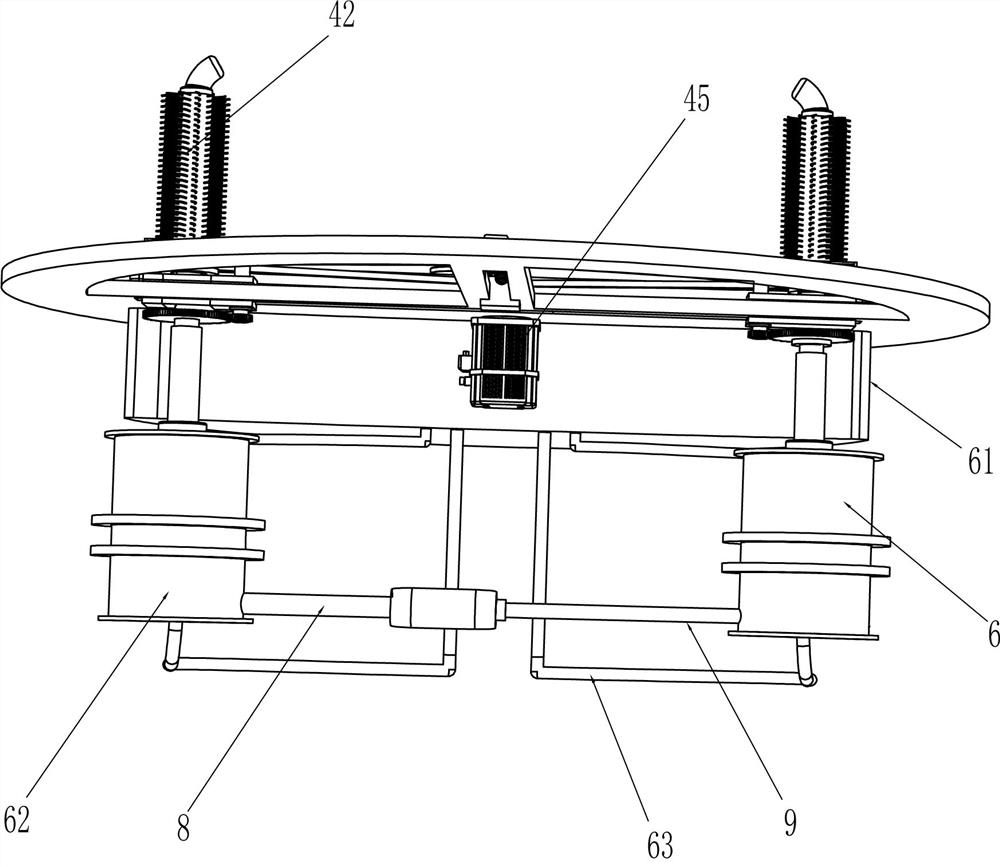
[0035] refer to figure 2 , Image 6 , Figure 7 with Figure 8 Compared with Embodiment 1, the main difference of this embodiment is that in this embodiment, a spray mechanism 6 is also included, and the spray mechanism 6 includes a liquid storage tank 61, a cylinder body 62, a one-way liquid inlet pipe 63, and a transmission assembly 64. Piston plate 65, three-way pipe 66, one-way valve 67, external thread liquid outlet pipe 68, movable nozzle pipe 69 and internal thread sleeve 610, cylinder body 62 is slidably connected to the front and rear sides of the bottom of rotating frame 2 , the cylinder body 62 is slidingly provided with a piston plate 65, the eccentric position of the piston plate 65 is connected with a three-way pipe 66, the upper and lower parts of the three-way pipe 66 are provided with a one-way valve 67, and the middle of the top of the cylinder body 62 passes through a sealing ring The sliding type is provided with an internal thread sleeve 610, and the b...

Embodiment 3

[0040] refer to figure 2 with Image 6 Compared with Embodiment 1 and Embodiment 2, the main difference of this embodiment is that in this embodiment, an L-shaped limiting plate 7 is also included, and the outer edge positions of the horizontal sliders 41 on the front and rear sides are fixedly connected with the L-shaped limiting plate. 7. The upper part of the L-shaped limiting plate 7 is located above the transmission gear 643 and the rotating gear 641 , and the derusting pipe 42 runs through the L-shaped limiting plate 7 .

[0041] Also include threaded rod 8 and threaded sleeve 9, the outer and rear lower part of the front side cylinder 62 is rotatably connected with threaded sleeve 9, the internal rotation of threaded sleeve 9 is provided with threaded rod 8, and the rear end of threaded rod 8 It is fixedly connected with the lower part of the outer front side of the rear side cylinder body 62 .

[0042] When the metal pipe is clamped and fixed by the clamping block 5...


PUM


Abstract

The invention relates to a rust removal device, in particular to a metal pipeline spiral part rust removal device. According to the metal pipeline spiral part rust removal device, comprehensive rust removal can be conducted on a spiral part of a metal pipeline, and follow-up use of the metal pipeline is not affected. The metal pipeline spiral part rust removal device comprises a circular ring base, a rotating frame is rotationally connected among the inner sides of four columns of the circular ring base, and a rocking handle is installed at the position, close to the circular ring base, of theeccentric position of the outer side of the rotating frame and penetrates through the circular ring base. By means of the device, the spiral part of the metal pipeline is moved to the position between rust removal pipes on the two sides, so that the rust removal pipes make contact with the spiral part of the metal pipeline, then the rust removal pipes are clamped and fixed through pipe clamping blocks, a drive motor is started, the rust removal pipes can rotate to remove rust on the spiral part of the metal pipeline, comprehensive rust removal can be conducted, and follow-up use is not affected.

Description

technical field [0001] The invention relates to a derusting device, in particular to a derusting device for the spiral part of a metal pipeline. Background technique [0002] A pipeline is a device used to transport gas, liquid or fluid with solid particles connected by pipes, pipe connectors and valves. Usually, after the fluid is pressurized by blowers, compressors, pumps and boilers, it flows from the high-pressure part of the pipeline to the low-pressure part, and it can also be transported by the pressure or gravity of the fluid itself. Pipes are widely used, mainly used in water supply, drainage, heat supply, gas supply, long-distance oil and natural gas transportation, agricultural irrigation, hydraulic engineering and various industrial installations. There will be metal pipes in the classification of pipes, and metal pipes are long The time of placement will make the spiral part rust, so it is necessary to derust the spiral part before use to facilitate the screw c...

Claims


Application Information

Patent Timeline
Patent Type & Authority Applications(China)
IPC IPC(8): B24B27/033B24B27/00B24B41/00B24B41/06B24B47/00B24B47/12B24B47/22B24B55/00B24B57/02
CPCB24B27/033B24B27/0076B24B47/12B24B41/067B24B47/22B24B57/02B24B41/00B24B55/00B24B47/00
Inventor 朱品淳
Owner 山东通洁科技工程有限公司
Why Eureka
Try Eureka