
Omnidirectional vehicle with variable-angle omnidirectional wheels

A technology of omni-directional wheels and corners, applied in the field of omni-directional vehicles, can solve the problems of increased installation compactness and reduced driving efficiency, and achieve the effects of improving driving efficiency, reducing driving dimensions, and reducing control difficulty

Inactive Publication Date: 2020-11-03
SHANGHAI JIAO TONG UNIV
View PDF6 Cites 2 Cited by
  • Summary
  • Abstract
  • Description
  • Claims
  • Application Information

AI Technical Summary

Problems solved by technology

However, in some motion states, such as when the platform moves forward in a straight line, if the fixed component force is still relied on, the driving efficiency will be reduced. If the installation angle of the rollers can be changed so that when moving forward, all component forces The main direction can be as consistent as possible with the direction of motion, which can improve the driving efficiency
[0003] In addition to the common mecanum wheel, the method to realize the omnidirectional movement of the platform can also be: add another degree of freedom of rotation perpendicular to the platform between the wheel and the platform, this kind of wheel is called the driving omnidirectional wheel, and the kinematics modeling is simple , but still needs to be improved in terms of installation compactness

Method used


Image

  • Omnidirectional vehicle with variable-angle omnidirectional wheels
  • Omnidirectional vehicle with variable-angle omnidirectional wheels
  • Omnidirectional vehicle with variable-angle omnidirectional wheels

Examples


Embodiment 1

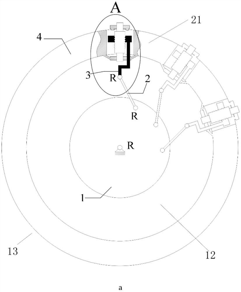
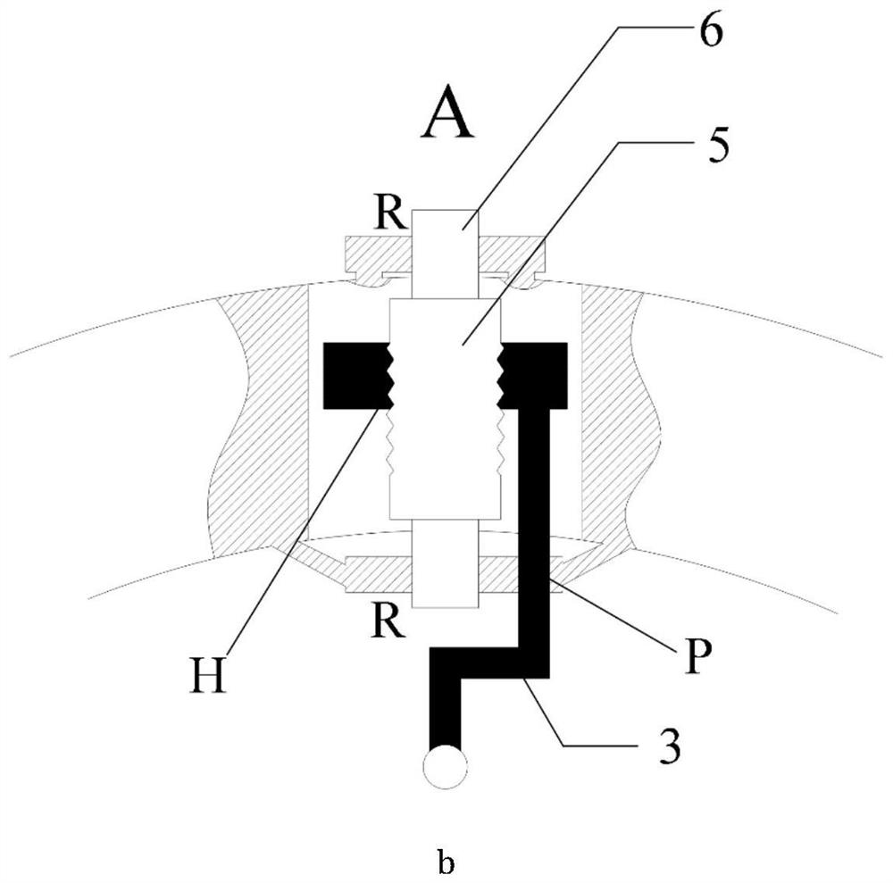
[0034] Such as figure 1 As shown, it is a variable-angle omnidirectional wheel 13 related to this embodiment, which includes: a turntable 23, a rotation angle adjustment device 12, a roller unit 14 and a connecting branch chain device 21, wherein: the rotation angle adjustment device 12 is arranged on the turntable 23 Above, the connecting branch chain device 21 is evenly arranged on the circumference of the rotation angle adjusting device 12 , and the roller unit 14 is connected with the rotation angle adjusting device 12 through the connecting branch chain device 21 .

[0035] The angle adjustment device 12 includes: a rotating active part 1, a connecting rod 2 and a supporting hub 4, wherein: the rotating active part 1 is arranged outside the turntable 23 and inside the supporting hub 4, and one end of the connecting rod 2 is evenly arranged on the rotating active part. On the circumference of part 1, the other end links to each other with connection branch chain device 21....

Embodiment 2

[0041] This embodiment relates to a variable-angle omnidirectional wheel 13, the basic structure of which is consistent with that of Embodiment 1, except that:

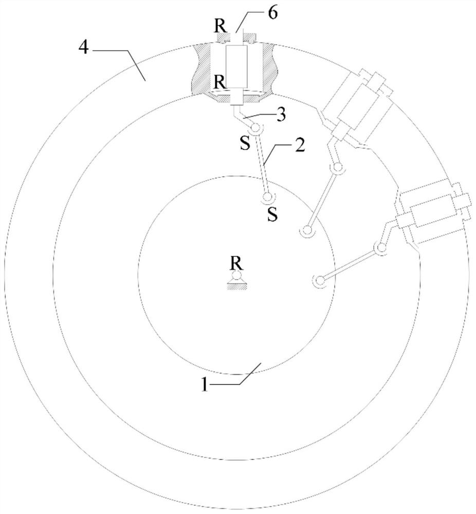
[0042] Such as figure 2 As shown, since the space RSSR and the circular plane are not in the same plane, the rotation of the rotating active part 1 will be transmitted to the end of the branch chain 6 through the space RSSR to make it rotate, and the roller fixedly connected to the end of the branch chain 6 (such as Figure 4 shown) the installation angle is changed.

[0043] Such as Figure 10 shown, for something like figure 2 Take the space RSSR mechanism as an example to realize the adjustment of the installation angle RIA of multiple rollers. The mechanism has n+1 branch chains, and each branch chain shares a turntable (that is, the "moving platform" in the parallel mechanism). Among the n+1 branch chains, one branch chain is the rotating pair R formed by the frame and the turntable. 1 , and the other n br...

Embodiment 3

[0045] This embodiment relates to a variable-angle omnidirectional wheel 13, the basic structure of which is consistent with that of Embodiment 1, except that the vehicle body includes: four second main drive shafts arranged at corners and independent of each other, wherein: the first The two main drive shafts are respectively connected with the variable-angle omnidirectional wheels.

[0046] Such as image 3 As shown, the described rotation angle adjustment device includes: a rotating active part 1, a connecting rod 2, a supporting hub 4, an action wheel 7 and an idler wheel 8, wherein: the rotating active part 1 is arranged in the supporting wheel hub 4, and the operating wheel 7 and the idler wheel The wheels 8 are successively arranged adjacently on the circumference of the rotating active part 1 , one end of the connecting rod 2 is connected with the action wheel, and the other end is connected with the connecting branch chain device 21 .

[0047] The rotating active par...


PUM


Abstract

A variable-angle omnidirectional wheel comprises a turntable, a corner adjusting device, a roller unit and a connecting branch chain device; the corner adjusting device comprises a rotary driving part, a connecting rod and a supporting hub; the connecting branch chain device comprises a branch chain, a lead screw and a nut. The roller unit comprises a supporting frame, a rotating pair and a roller, wherein the supporting frame is arranged at the tail end of the branched chain, and the roller is movably arranged in the supporting frame through the rotating pair. An omnidirectional vehicle withthe variable-angle omnidirectional wheels comprises a vehicle body and the four variable-angle omnidirectional wheels. The rotary motion of the central shaft is converted into the rotary motion of theplurality of rollers which are perpendicular to the axis and are uniformly distributed on the circumference through the corner adjusting device, and the rollers can synchronously rotate at any mounting angle under the action of the corner adjusting device without mutual interference; the change of the installation angle of the roller enables the direction of a friction force given to the roller by the ground to be variable, the omnidirectional flexibility is further improved, omnidirectional movement of the platform can be achieved, and both installation compactness and advancing efficiency under different movement states can be considered.

Description

technical field [0001] The invention relates to a technology in the field of transportation automation, in particular to an omnidirectional vehicle with variable-angle omnidirectional wheels. Background technique [0002] Mecanum wheels, Omni wheels, etc. are widely used in omnidirectional mobile systems. This is because the axes of the rollers evenly arranged on the circumference form an angle with the center line of the circumference. According to four or more mecanum The component force combination of the Omni wheel and the Omni wheel enables the platform to move in various poses. However, in some motion states, such as when the platform moves forward in a straight line, if the fixed component force is still relied on, the driving efficiency will be reduced. If the installation angle of the rollers can be changed so that when moving forward, all component forces The main direction can be consistent with the direction of motion as much as possible, so that the driving eff...

Claims


Application Information

Patent Timeline
Patent Type & Authority Applications(China)
IPC IPC(8): B60B19/00B60B19/12
CPCB60B19/003B60B19/125
Inventor 郭为忠王旭
Owner SHANGHAI JIAO TONG UNIV
Learn More