
Winding equipment special for melt-blowing production

A special roll and melt-blown technology, which is applied in the direction of winding strips, sending objects, thin material processing, etc., can solve the problem of inability to realize automatic loading and unloading, uneven incision edges of melt-blown cloth, and reduced worker productivity, etc. problems, to achieve the effect of novel structure, reduced manpower consumption, and stable structure

Inactive Publication Date: 2020-11-03
崔建中
View PDF6 Cites 7 Cited by
  • Summary
  • Abstract
  • Description
  • Claims
  • Application Information

AI Technical Summary

Problems solved by technology

When the existing melt-blown cloth winding equipment is wound, it is necessary to manually transport the wound drum to the transfer vehicle for transfer, and at the same time, it is also necessary to manually place the new drum at the designated winding position so that the equipment can continue to roll. Therefore, the equipment needs to be equipped with two workers to place the reel on the reel frame during operation, which reduces the production efficiency of the workers and cannot realize automatic loading and unloading; When the drum is wound and cut, the slit melt blown cloth is cut horizontally by the lateral movement of the cutter, and then wound onto a new drum, which is prone to uneven edges of the cut of the melt blown cloth, resulting in waste of materials. Moreover, it is easy to cause stacking during winding, which affects the winding quality, so the existing winding equipment cannot meet the needs of workshop automation and high-quality production

Method used


Image

  • Winding equipment special for melt-blowing production
  • Winding equipment special for melt-blowing production
  • Winding equipment special for melt-blowing production

Examples


Embodiment Construction

[0027] In order to make the technical solution of the present invention clearer, the present invention will be further described below in conjunction with the accompanying drawings. Any solution obtained by equivalent replacement and conventional reasoning of the technical features of the technical solution of the present invention falls within the protection scope of the present invention. The fixed connection mentioned in the present invention and the fixed arrangement are common connection methods in the mechanical field, and welding, bolt and nut connection and screw connection are all available.

[0028] In describing the present invention, it is to be understood that the terms "upper", "lower", "front", "rear", "left", "right", "vertical", "horizontal", "top" , "bottom", "inner", "outer" and other indicated orientations or positional relationships are based on the orientations or positional relationships shown in the drawings, and are only for the convenience of describin...


PUM


Abstract

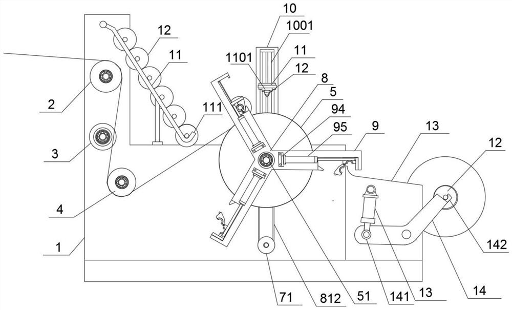
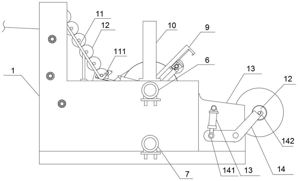
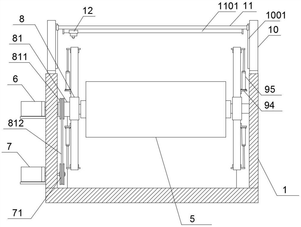
The invention relates to winding equipment special for melt-blowing production. The equipment comprises a rack, a guide roller, a slitting knife, a conveying roller and a power roller are sequentiallyarranged on the rack, feeding frames are arranged on the two sides of the upper end of the rack, limiting ends are arranged at the lower ends of the feeding frames, a plurality of rollers are placedon the feeding frames, and the two shaft ends of each roller are limited through the limiting ends. The two shaft ends of the power roller are rotationally arranged on the rack, and feeding mechanismsare arranged at the two shaft ends of the power roller and sequentially feed the rollers on the feeding frames. A laser cutting mechanism is arranged at the top end of the middle part of the rack andis used for transversely cutting melt-blown cloth on the power roller. The two sides of one end of the rack are connected with discharging plates, the distance between the two discharging plates is smaller than the distance of the rack, the upper ends of the discharging plates are obliquely arranged downwards, discharging mechanisms are arranged on the discharging plates, and the discharging mechanisms discharge wound rollers to a transfer trolley. The winding equipment is stable in structure and high in working efficiency, automatic feeding and discharging are achieved, and manpower consumption is reduced.

Description

technical field [0001] The invention belongs to the technical field of melt-blown cloth manufacturing, and in particular relates to a special winding equipment for melt-blown production. Background technique [0002] The manufacture of nonwovens by meltblown method is a general and cost-effective method of directly producing nonwoven fabrics with microfiber structures from polymers. Meltblown nonwovens have excellent filterability, shielding, heat insulation and Oil absorption, so it is widely used in medical, heat preservation, filtration, adsorption, and sound insulation and other fields. Melt-blown cloth needs to be wound up on a drum after the cloth is formed for easy storage and transportation. When the existing melt-blown cloth winding equipment is wound, it is necessary to manually transport the wound drum to the transfer vehicle for transfer, and at the same time, it is also necessary to manually place the new drum at the designated winding position so that the equi...

Claims


Application Information

Patent Timeline
IPC IPC(8): B65H20/04B65H35/02B65H19/30
CPCB65H19/30B65H20/04B65H35/02
Inventor 崔建中
Owner 崔建中
Learn More