
Bladeless cold and hot powerful ceiling fan lamp

A leafless, ceiling fan lamp technology, applied in the field of ceiling fan lamps, can solve the problems such as no ceiling fan, no hot air for heating, low wind pressure, etc., to increase heating and heating functions, facilitate viewing and operation, and improve the effect of air supply

Pending Publication Date: 2020-11-03
GUANGDONG FUNAITE ELECTRIC
View PDF0 Cites 1 Cited by
  • Summary
  • Abstract
  • Description
  • Claims
  • Application Information

AI Technical Summary

Problems solved by technology

However, the above-mentioned ceiling fan lamp still has the following disadvantages: (1) the fan blade is movably arranged on the rotating disk through the extension and reset mechanism, and its structure is complicated, the process is difficult, and the cost is high; (2) the fan blade Always on the top wall of the rotating disk, that is: the fan blades are always exposed, easy to accumulate dust, and need to be assembled and disassembled frequently, causing great inconvenience to users; (3) Single function, only cool (cold) air can be blown out to cool down , can not blow out hot air for heating, therefore, the part that cannot be used for ceiling fans cannot be used in four seasons; (4) leafless ceiling fan lights, due to the small air pressure in the air duct, the air output is also small

Method used


Image

  • Bladeless cold and hot powerful ceiling fan lamp
  • Bladeless cold and hot powerful ceiling fan lamp
  • Bladeless cold and hot powerful ceiling fan lamp

Examples


Embodiment Construction

[0026] The present invention will be further described below in conjunction with drawings and embodiments.

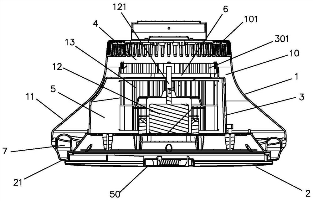
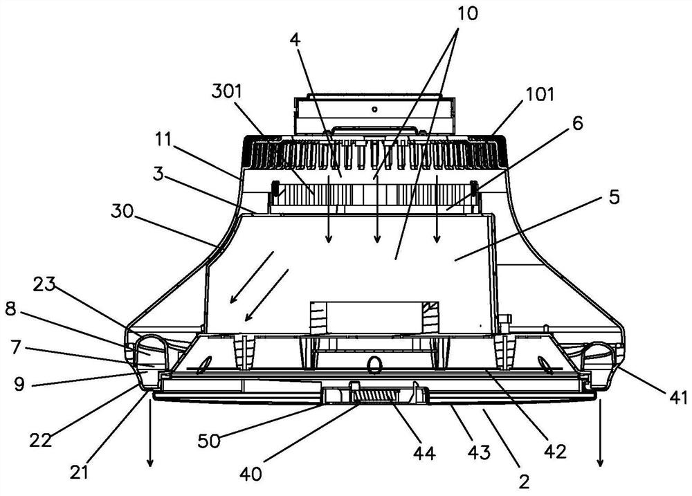
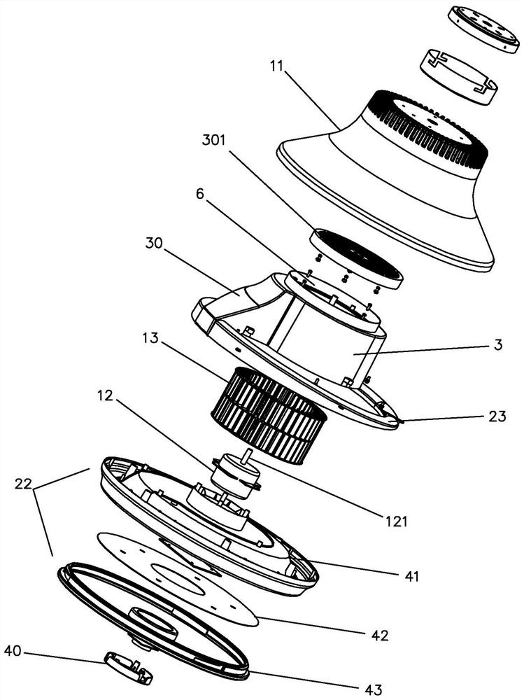
[0027] Such as Figure 1 to Figure 5 As shown, a bladeless cold and hot powerful ceiling fan lamp includes a fan part 1, a lamp part 2 and an electric heating element 301, the fan part 1 is arranged on the upper part of the lamp part 2, and the fan part 1 includes a windshield 11 , motor 12 and wind wheel 13, described wind cover 11 is provided with air duct 10, and air duct 10 is provided with air inlet 101 and air outlet 102, and described wind wheel 13 is connected with described motor 12 and is installed on wind cover 11 together On the air duct 10 inside, the electric heating element 301 is arranged on the air duct 10 between the wind wheel 13 and the air inlet 101, and the lamp part 2 is provided with an air outlet 21, and the air outlet 102 is connected to the air outlet 21, which The feature is that a section of the air duct 10 between the wind wheel 13 and the...


PUM


Abstract

The invention discloses a bladeless cold and hot powerful ceiling fan lamp, and the lamp comprises a fan part, a lamp part and an electric heating body, wherein the fan part is arranged on the upper portion of the lamp part; the fan part comprises a fan cover, a motor and a wind wheel, wherein an air duct is arranged on the fan cover, and an air inlet and an air outlet are formed in the air duct;the wind wheel is connected with the motor and installed on an air duct in the fan cover together with the motor, the electric heating body is arranged on the air duct between the wind wheel and the air inlet, the lamp part is provided with an air supply outlet, the air outlet is connected with the air supply outlet, wherein one section of the air duct between the wind wheel and the air outlet isa powerful air supply section and is arranged in the air outlet direction, and the inner diameter of the air duct of the powerful air supply section is gradually reduced. According to the invention, the ceiling fan lamp is simple in structure, small in process difficulty and low in cost, the wind wheel is not exposed, dust is not prone to being accumulated, the heating function is added, the innerdiameter of the air duct of the powerful air supply section close to the air supply outlet is gradually decreased, powerful air pressure is formed in the powerful air supply section, and the air outlet amount is obviously increased.

Description

technical field [0001] The invention relates to the technical field of ceiling fan lamps, in particular to a bladeless cold and hot powerful ceiling fan lamp. Background technique [0002] Traditional ceiling fan lamps, such as: the fan blade is a hidden ceiling fan lamp, the lower part is a lamp, and the upper part is a fan. The fan includes a rotating disc, a fan blade and a motor. The fan blade is set on the rotating disc through an extension and reset mechanism. The motor drives the rotating disc to rotate, thereby driving the fan blades to rotate. Under the action of centrifugal force, at least a part of the fan blades are thrown out of the rotating disc to realize the extension of the fan blades; when the motor stops working, the rotating disc stops rotating, and the fan blades are reset. Thereby retracting into the rotating disc to realize the hidden effect of the fan blades. However, the above-mentioned ceiling fan lamp still has the following disadvantages: (1) the...

Claims


Application Information

Patent Timeline
IPC IPC(8): F21S8/00F21V23/00F21V33/00F24H3/04F24H9/20F04D25/08F04D29/42F04D29/58F04D29/00F04D27/00
CPCF04D25/088F04D27/00F04D27/004F04D29/002F04D29/4226F04D29/582F05D2270/303F21S8/00F21V23/003F21V33/0044F24H3/0405F24H9/2071
Inventor 谢刚高用忠
Owner GUANGDONG FUNAITE ELECTRIC
Learn More