Eureka AIR delivers breakthrough ideas for toughest innovation challenges, trusted by R&D personnel around the world.

A Blasting Method Applicable to Alternate Rock Mass with Soft and Hard Structural Surfaces

A technology for weak structural surfaces and structural surfaces, which can be used in blasting, earthwork drilling, wellbore/well components, etc., and can solve problems such as energy leakage and uneven damage in weak structural layers

Active Publication Date: 2021-03-30
INST OF ROCK & SOIL MECHANICS CHINESE ACAD OF SCI
View PDF8 Cites 0 Cited by
  • Summary
  • Abstract
  • Description
  • Claims
  • Application Information

AI Technical Summary

Problems solved by technology

This method can improve the blasting situation in the homogeneous and complete rock mass, but it cannot solve the problems of energy leakage and uneven damage caused by the existence of weak structural layers, and cannot fundamentally solve the problems caused by the interlacing of soft and hard structural planes and the development of cracks. existing problems

Method used


Image

  • A Blasting Method Applicable to Alternate Rock Mass with Soft and Hard Structural Surfaces
  • A Blasting Method Applicable to Alternate Rock Mass with Soft and Hard Structural Surfaces
  • A Blasting Method Applicable to Alternate Rock Mass with Soft and Hard Structural Surfaces

Examples


Embodiment 1

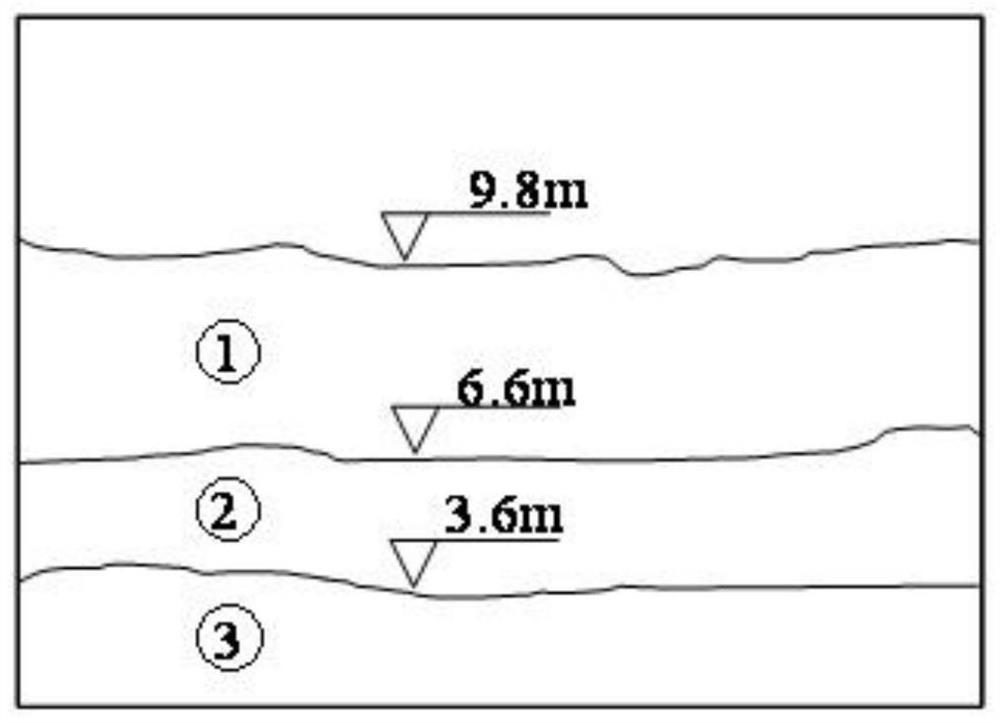
[0154] Embodiment 1: see figure 2 As shown, it is a schematic diagram of the geological situation of an embodiment of a rock mass with soft and hard structural surfaces to be blasted that is detected by the blasting method of the present invention. figure 2 Among them, the first and third layers are granite, and the strength of granite is 127MPa, and the elastic modulus is 32GPa; the second layer is slate, and the strength of slate is 45MPa, and the elastic modulus is 21GPa; In addition, in There is an east-west micro-crack inside the granite of the first layer; there is no crack inside the granite of the third layer; there are two main cracks inside the slate of the second layer.

[0155] According to the scoring method in the above rock mass parameter scoring table 1, it can be obtained:

[0156] The rock mass parameter score corresponding to the first layer of granite is F1=1 (that is, the score corresponding to the strength)+1 (that is, the score corresponding to the el...

Embodiment 2

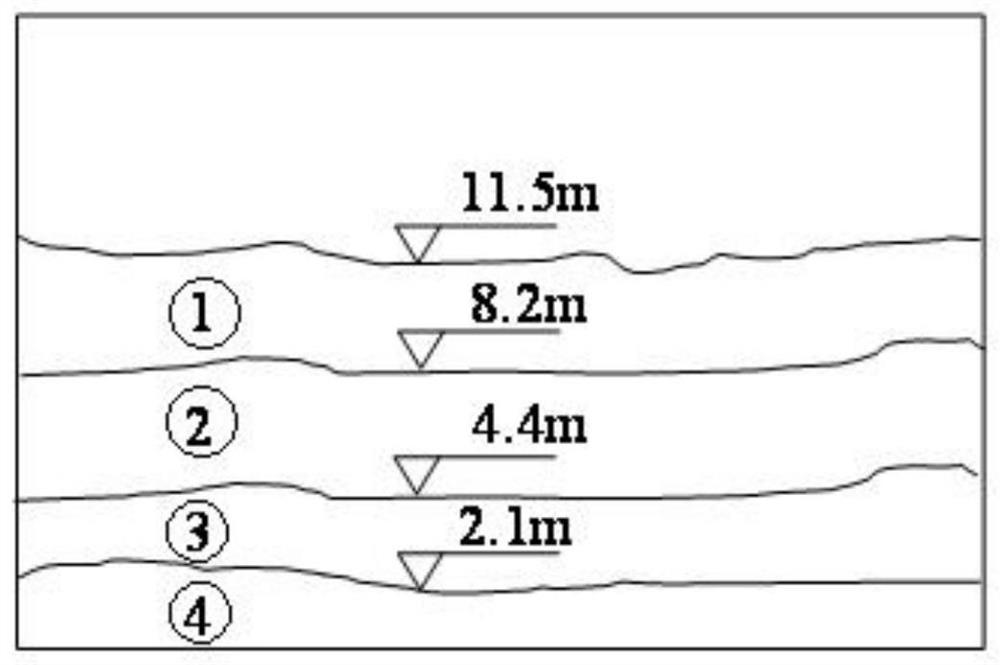
[0164] Embodiment 2: see image 3 As shown, it is a schematic diagram of the geological situation of another rock mass embodiment with soft and hard structural surfaces to be blasted by the blasting method of the present invention. image 3 Among them, the first layer and the third layer are both sandstone, and the strength of sandstone is 67MPa, and the elastic modulus is 27GPa; the second layer is mudstone, and the strength of mudstone is 23MPa, and the elastic modulus is 12GPa; the fourth layer is mudstone The strength of argillaceous sandstone is 31MPa, and the elastic modulus is 17MPa; in addition, there is a micro-crack in the first layer of sandstone; there is a main crack in the second layer of mudstone; in the third layer of sandstone No cracks exist; there is 1 micro-crack inside the fourth layer of argillaceous sandstone.

[0165] According to the scoring method in the above rock mass parameter scoring table 1, it can be obtained:

[0166] The rock mass parameter ...


PUM


Abstract

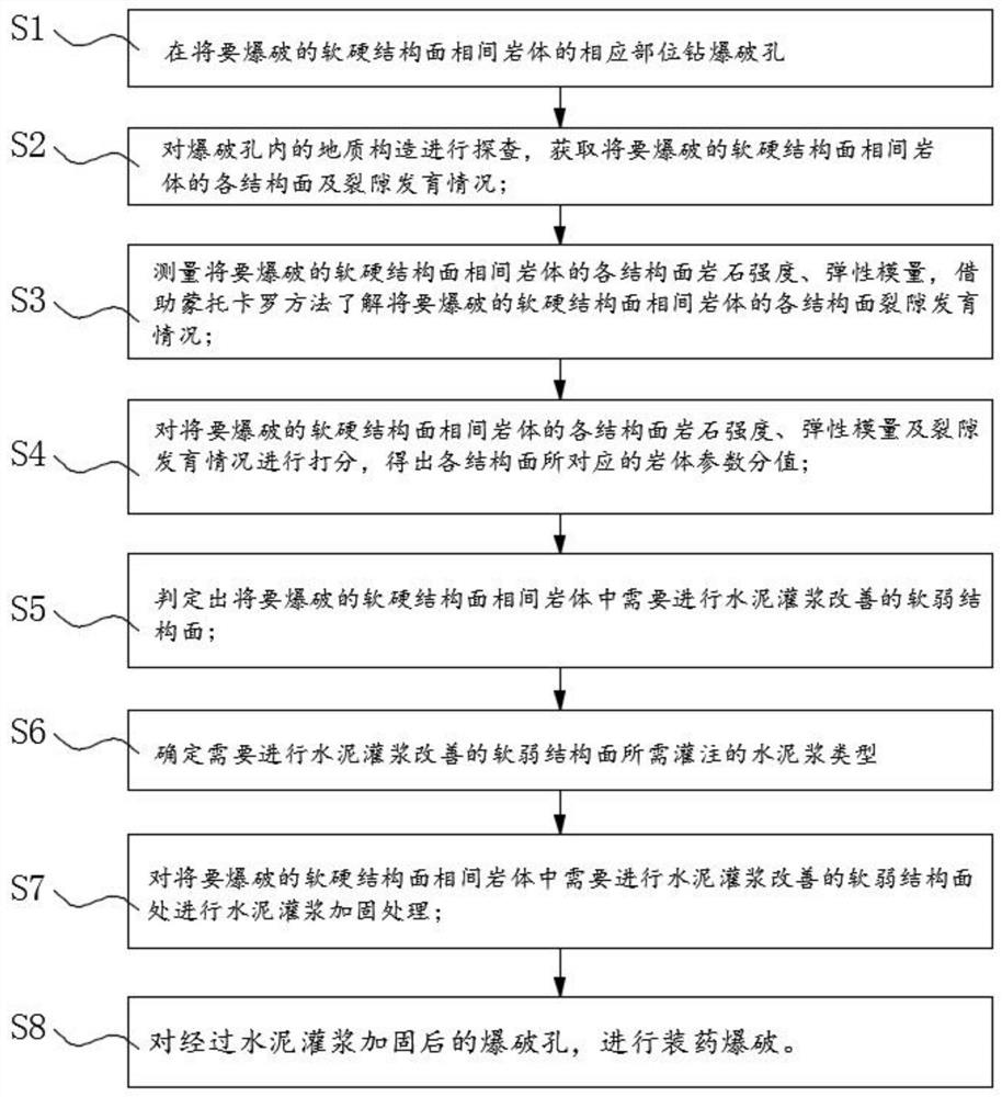
The invention discloses a blasting method suitable for soft and hard structural surface alternate rock masses. The blasting method comprises the following steps of obtaining all structural surfaces and crack development conditions of the soft and hard structural surface alternate rock masses to be blasted; measuring the rock strength and the elasticity modulus of each structural surface; scoring the rock strength, the elasticity modulus and the crack development condition of each structural surface to obtain a rock mass parameter score of each structural surface; determining a weak structuralsurface needing cement grouting for improvement according to the rock mass parameter score; determining the type of cement paste needing to be poured according to the rock mass parameter score of theweak structural surface needing to be improved by cement grouting; performing cement grouting reinforcement on the weak structural surface by using a cement grouting device; and carrying out chargingblasting on blasting holes reinforced through cement grouting. The method has the advantages that slurry can be accurately injected into the weak structural surface, so that the strength of the weak structural surface is improved, the lithology differentiation between different rock masses is reduced, and the problem of explosive shock wave leakage at the weak structural surface can be effectivelyavoided.

Description

technical field [0001] The invention relates to the technical field of rock-soil blasting, in particular to a blasting method suitable for rock mass between soft and hard structural surfaces. Background technique [0002] In the process of open-pit mining, underground tunnel drilling and blasting excavation, and water conservancy and hydropower construction rock mass excavation, more and more structurally complex geological conditions are encountered, such as: soft and hard structural planes are interlaced with rock mass, and cracks are developed, resulting in Explosive energy leaks in the hole, and the insufficient utilization rate causes large pieces, roots and flying stones. Therefore, more stringent safety measures and secondary blasting are often required, which also causes slow progress and increased costs. Among them, rock masses with soft and hard structural planes alternate with each other, and cracks often co-exist. In order to solve the above problems, the industr...

Claims


Application Information

Patent Timeline
Patent Type & Authority Patents(China)
IPC IPC(8): F42D1/00F42D3/04E21B33/13
CPCE21B33/13F42D1/00F42D3/04
Inventor 武仁杰李海波李晓锋刘黎旺
Owner INST OF ROCK & SOIL MECHANICS CHINESE ACAD OF SCI
Why Eureka
Eureka Blog
Learn More