
Highway and bridge deck pavement interlayer shear tester and method considering centrifugal force

A bridge deck paving and interlaminar shearing technology, applied in the direction of applying stable shear force to test material strength, instruments, measuring devices, etc., can solve the problem of single function, without considering the influence of centrifugal force interlaminar shear stress, It cannot effectively simulate the shear stress conditions of curved girder bridge deck roads, etc., to achieve the effect of good practicability, high degree of simulation, and wide application range.

Pending Publication Date: 2020-11-03
UNIV OF SCI & TECH LIAONING
View PDF0 Cites 0 Cited by
  • Summary
  • Abstract
  • Description
  • Claims
  • Application Information

AI Technical Summary

Problems solved by technology

[0003] However, the existing interlayer shear instruments for road and bridge deck pavement have a single function, and can only simulate the shear stress between the pavement of the straight road section of the highway and the bridge deck pavement of the straight bridge. Although some shear instruments have been improved to a certain extent, The influence of a certain longitudinal slope on the interlayer shear stress is considered, but the existing shear instruments are still unable to effectively simulate the shear stress between the layers of the curved beam bridge deck pavement and the road curve, mainly because the existing shear The instrument does not consider the influence of centrifugal force on the interlayer shear stress, and at the same time, it cannot realize the test of different longitudinal slopes on the interlayer shear stress

Method used


Image

  • Highway and bridge deck pavement interlayer shear tester and method considering centrifugal force
  • Highway and bridge deck pavement interlayer shear tester and method considering centrifugal force
  • Highway and bridge deck pavement interlayer shear tester and method considering centrifugal force

Examples


Embodiment Construction

[0062] The specific embodiment of the present invention will be further described below in conjunction with accompanying drawing:

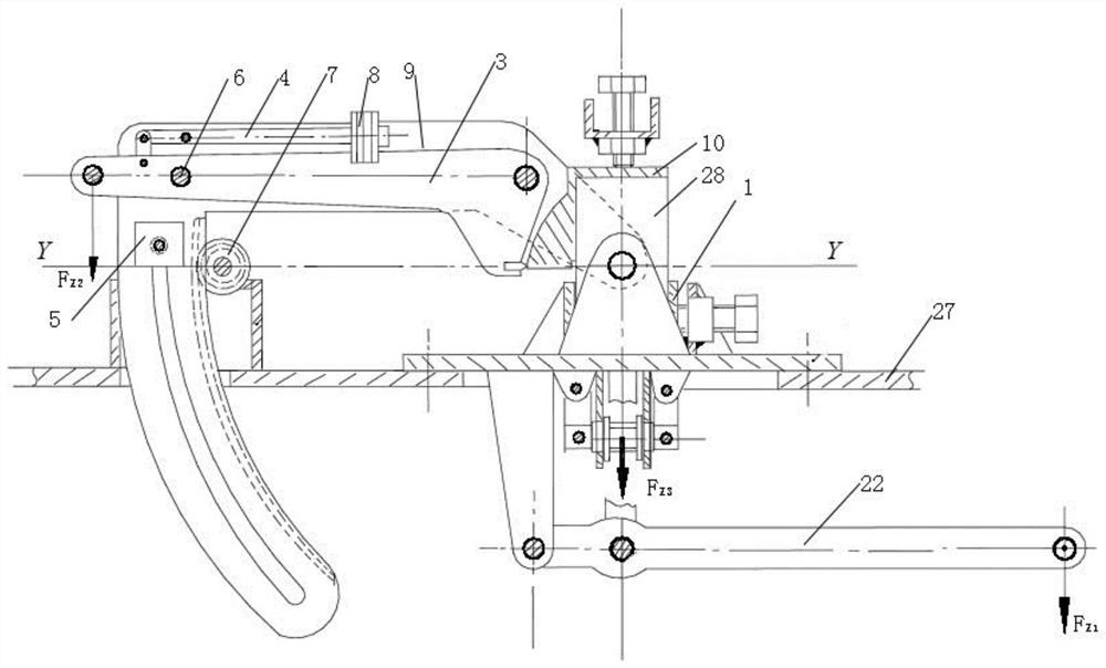
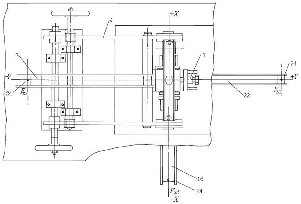
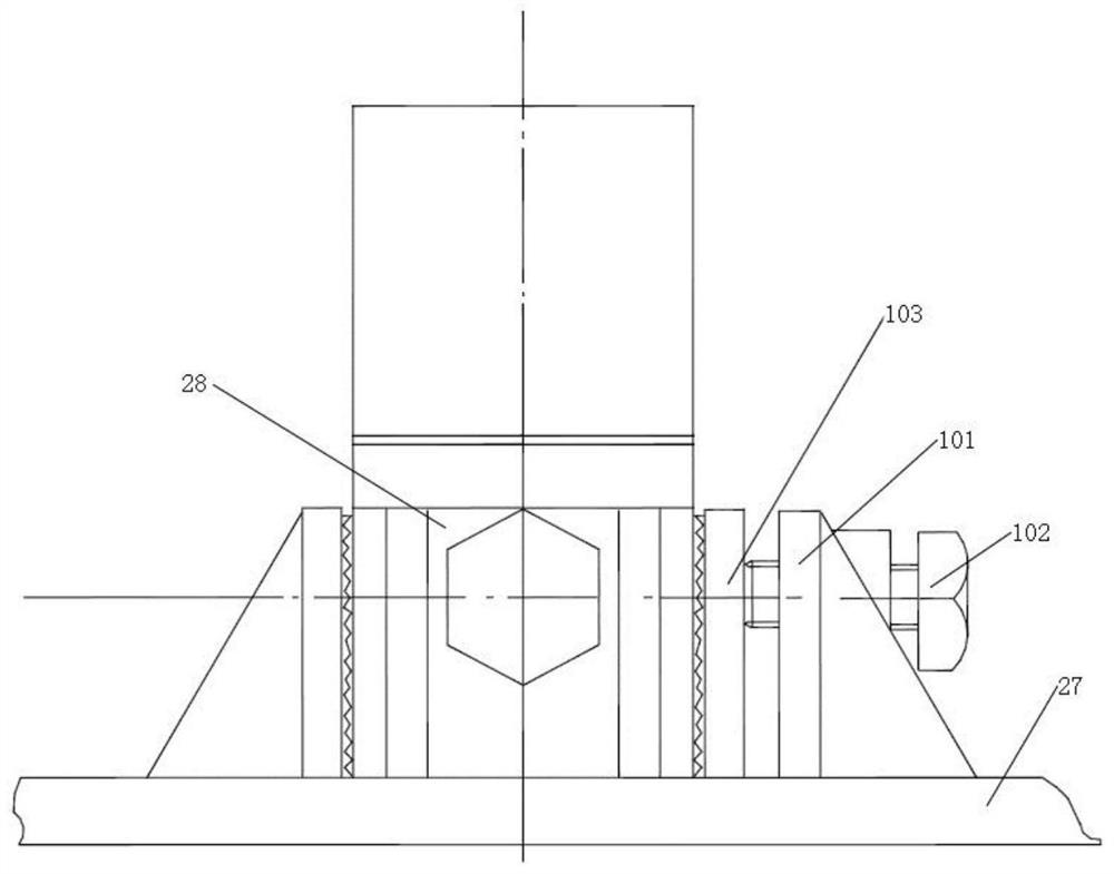
[0063] Such as Figure 1-9 As shown, a highway and bridge deck interlayer shear tester considering centrifugal force, including F Z1 Loading lever 22, F Z2 Loading lever 3, F Z3 Loading lever 16, specimen clamping device 1, angle adjustment arm 9, counterweight 8, adjustment locking device 5, self-weight balance lever 4, first pressing blade 14, second pressing blade 19, fixed pulley 2, upper beam 20 , the lower cross shaft 25, the adjusting bolt 26, the first pull rod 17, the second pull rod 21 and the fulcrum arm 23. f Z2 The loading lever 3 is hinged on the angle adjustment arm 9, and the angle adjustment arm 9 is hinged on the upper side of the main abutment surface 27, F Z1 Loading lever 22, F Z3 The loading lever 16 is hinged on the underside of the main abutment surface 27, F Z3 The loading lever 16 is located on the negative half ax...


PUM


Abstract

The invention relates to the technical field of highway pavement and bridge deck pavement, in particular to a highway and bridge deck pavement interlayer shear tester and method considering centrifugal force. The tester comprises an FZ1 loading lever, an FZ2 loading lever, an FZ3 loading lever, a test piece clamping device, an angle adjusting arm, an adjusting and locking device, a self-weight balance lever, a first pressing blade and a second pressing blade, wherein the FZ2 loading lever is hinged to the angle adjusting arm; the angle adjusting arm is hinged to the upper side of a main base table board, and the FZ1 loading lever and the FZ3 loading lever are hinged to the lower side of the main base table board; the adjusting and locking device adjusts the angle of the angle adjusting armand locks the angle adjusting arm, and a self-weight balance lever provided with a balance weight is hinged to the angle adjusting arm and the FZ2 loading lever; the test piece clamping device clampsa test piece; the first pressing blade is fixedly connected to the FZ2 loading lever; and the second pressing blade is fixedly connected to the FZ3 loading lever. Influences of longitudinal slopes, centrifugal force and the like on interlayer shearing stress are considered, and the shearing stress conditions of curved beam bridge deck pavement interlayers and highway bends can be effectively simulated.

Description

technical field [0001] The invention relates to the technical field of highway pavement and bridge deck pavement, in particular to an interlayer shear tester and method for road and bridge deck pavement considering centrifugal force. Background technique [0002] The interlayer connection of highway pavement (between the asphalt concrete layer and the asphalt concrete layer, between the cement concrete pavement and the asphalt concrete overlay, and between the bridge deck pavement) has always been a problem that the highway industry attaches great importance to. my country's asphalt concrete The interlayer interface bonding between layers and cement-stabilized layers and between asphalt concrete layers is relatively weak, in an intermediate state between complete sliding and complete continuity, and stress is transmitted between layers through contact. In this way, the actual working state of the asphalt pavement does not match the design theoretical working state, which dire...

Claims


Application Information

Patent Timeline
IPC IPC(8): G01N3/02G01N3/04G01N3/24
CPCG01N3/02G01N3/04G01N3/24
Inventor 田帅苗振坤孙博张功胡文静李涛
Owner UNIV OF SCI & TECH LIAONING
Learn More