Visual inspection equipment for medical balloon

A visual inspection and equipment technology, which is applied in the direction of measuring devices, optical testing of flaws/defects, and material analysis through optical means, can solve the inconvenient maintenance of internal components of the cabinet, low efficiency, and the inability to ensure timely observation of medical balloons To ensure the timeliness of observation, improve efficiency, and facilitate maintenance

Pending Publication Date: 2020-11-03
昆山嘉斯特自动化技术有限公司
View PDF5 Cites 0 Cited by
  • Summary
  • Abstract
  • Description
  • Claims
  • Application Information

AI Technical Summary

Problems solved by technology

[0009] The purpose of the present invention is to provide a visual detection device for medical balloons, to solve the problem of low efficiency of visual detection of medical balloons in the prior art, real-time observation of the visual detection process of medical balloons in the cabinet, and The maintenance of the internal components of the cabinet is inconvenient, and the timeliness of the observation of the visual inspection results of the medical balloon cannot be guaranteed.

Method used


Image

  • Visual inspection equipment for medical balloon
  • Visual inspection equipment for medical balloon
  • Visual inspection equipment for medical balloon

Examples


Embodiment Construction

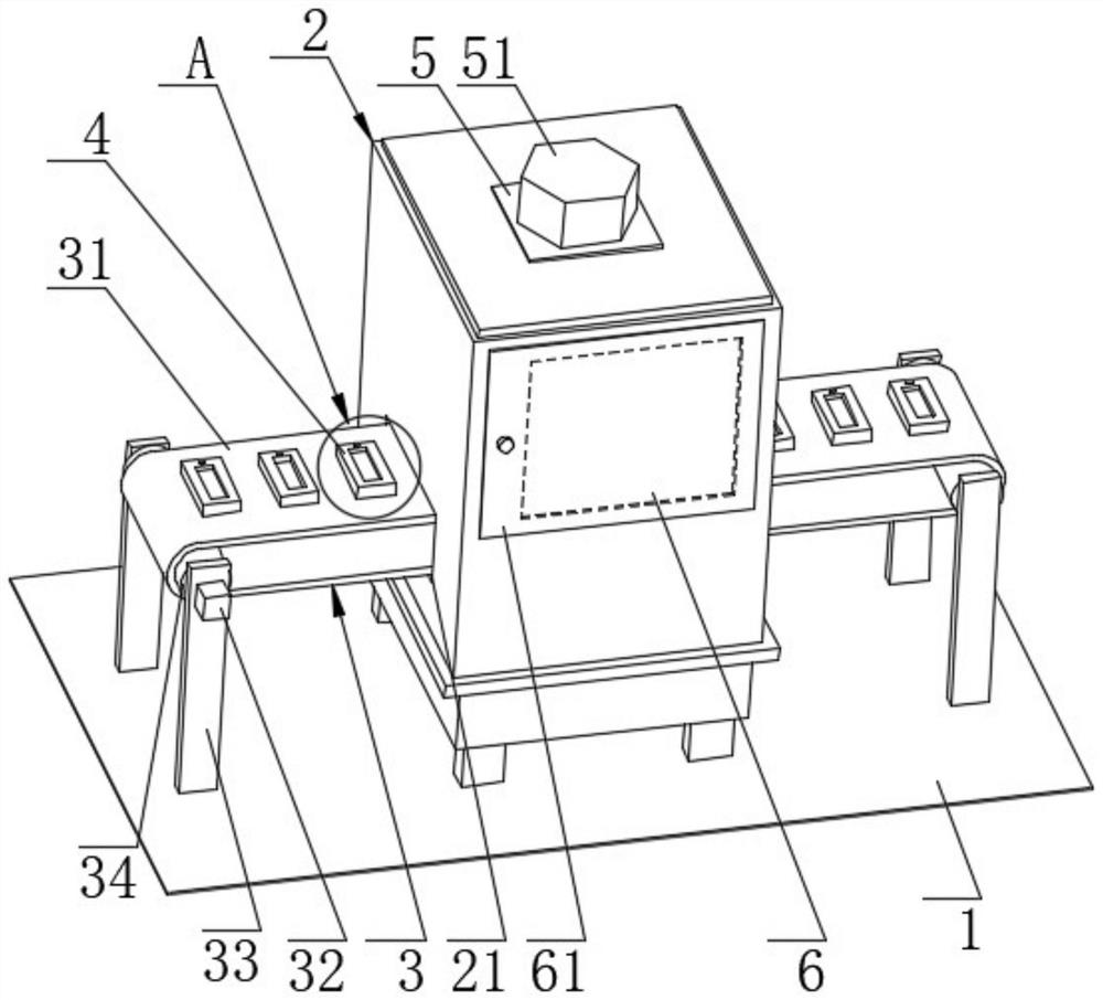
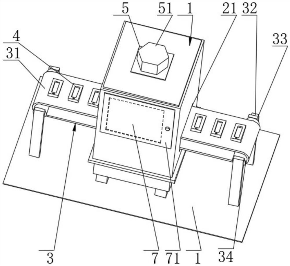
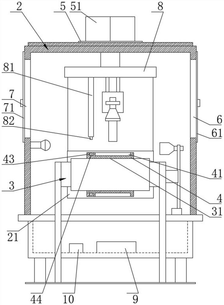
[0030] see figure 1 , figure 2 , image 3 , Figure 4 , Figure 5 , a visual inspection device for medical balloons, comprising a cabinet body 2, and a conveyor belt main body 3 arranged on a fixed surface 1, a delivery opening 21 is opened on the left and right side plates of the cabinet body 2, and the conveyor belt body 3 is driven by a belt 31 , a motor 32, a bracket 33, a roller 34, and a placement block 4. The belt 31 and the placement block 4 run through the conveying opening 21 as a whole. The size of the structure is not smaller than the overall lateral dimensions of the belt 31 and the placement block 4. The motor 32 is mounted on the bracket 33 through screws. 34 on the outer wall surface, the placement block 4 and the belt 31 are fixedly bonded by resin glue, and the number of placement blocks 4 is twenty and arranged along the outer wall surface of the belt 31. The placement block 4 is provided with a detection groove 41, a concave Groove 43, the top view se...


PUM


Abstract

The visual inspection equipment comprises a cabinet body, conveying openings are formed in a left side plate and a right side plate of the cabinet body, a first side cover and a second side cover arearranged on the front side plate and the rear side plate of the cabinet body, a belt and a placement block integrally penetrate through the conveying openings, a detection groove and a groove are formed in the placement block, and a detected block is arranged in the groove; a transverse plate is arranged on the upper portion of an inner cavity of the cabinet body, a connecting rod is arranged at the lower left end of the transverse plate, a photoelectric switch is arranged at the lower end of the connecting rod, a processor and a controller are arranged on the lower portion of the inner cavityof the cabinet body, and a hexagonal cover and an indicator lamp set are arranged at the upper end of a top plate of the cabinet body. According to the invention, the medical balloon placed in the detection groove is detected in a conveying mode, the efficiency of visual detection of the medical balloon is improved, real-time observation of the visual detection process of the medical balloon in the cabinet body is achieved, parts in the cabinet body are conveniently overhauled through the observation opening, and the observation timeliness of the visual detection result of the medical balloonis guaranteed.

Description

technical field [0001] The invention belongs to the technical field of visual inspection equipment, in particular to a visual inspection equipment for medical balloons. Background technique [0002] Endovascular angioplasty is to send a balloon catheter into the stenotic part of the blood vessel through percutaneous puncture intervention, and use the expansion of the medical balloon to restore the diameter of the stenotic vessel lumen and increase the blood flow. Therefore, for the medical balloon The overall shape and size requirements are relatively high. [0003] In the process of mass production of medical balloons, the overall shape inspection is required, and visual inspection equipment is often used. Visual inspection equipment uses machines instead of human eyes for measurement and judgment. Visual inspection refers to the use of machine vision products (ie image The ingestion device (CMOS and CCD) converts the ingested object into an image signal, and transmits it ...

Claims


Application Information

Patent Timeline
Patent Type & Authority Applications(China)
IPC IPC(8): G01N21/89G01N21/01B65G15/00
CPCG01N21/89G01N21/01B65G15/00
Inventor 王芳曾峰姜嘉浩
Owner 昆山嘉斯特自动化技术有限公司
Why Eureka
Try Eureka