
Self-focusing method for high-resolution moving ship SAR imaging

A high-resolution, self-focusing technology, applied in the field of self-focusing of high-resolution moving ship SAR imaging, can solve the problems of large amount of calculation, complicated process, and inability to meet high-resolution imaging of ships, so as to improve the focusing effect and realize accurate focus effect

Active Publication Date: 2020-11-03
XIDIAN UNIV
View PDF12 Cites 8 Cited by
  • Summary
  • Abstract
  • Description
  • Claims
  • Application Information

AI Technical Summary

Problems solved by technology

However, in the high-resolution SAR imaging of ship targets on the sea, due to the movement of the ship within the coherent processing time (CPI), unknown motion errors not only exist in the radar platform, but also in the ship target, so the traditional autofocus method cannot Meet the needs of high-resolution imaging of ships
At the same time, in recent years, most of the research on the self-focusing of moving ship imaging needs to calculate the phase error of pulse by pulse through one-dimensional search, and the phase error of each pulse needs to be iteratively estimated multiple times, the process is complicated and the calculation amount is large. There are certain limitations

Method used


Image

  • Self-focusing method for high-resolution moving ship SAR imaging
  • Self-focusing method for high-resolution moving ship SAR imaging
  • Self-focusing method for high-resolution moving ship SAR imaging

Examples


Embodiment Construction

[0030] Embodiments of the present invention will be described in detail below in conjunction with examples, but those skilled in the art will understand that the following examples are only used to illustrate the present invention, and should not be considered as limiting the scope of the present invention.

[0031] First, the selection of platform motion and phase error compensation mode of the present invention is described:

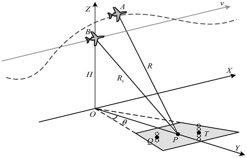
[0032] refer to figure 1 It is a schematic diagram of the SAR imaging model of a moving ship; the platform flies along the x-axis direction, its speed is v, the flight height is H, P is the center point of the scene, and is also the center point of a ship target, and the corresponding ideal slant distance is R s . In an ideal situation, the platform will fly at a constant speed and in a straight line along the track indicated by the solid line. However, in actual situations, due to atmospheric turbulence, platform instability and other reasons, the f...


PUM


Abstract

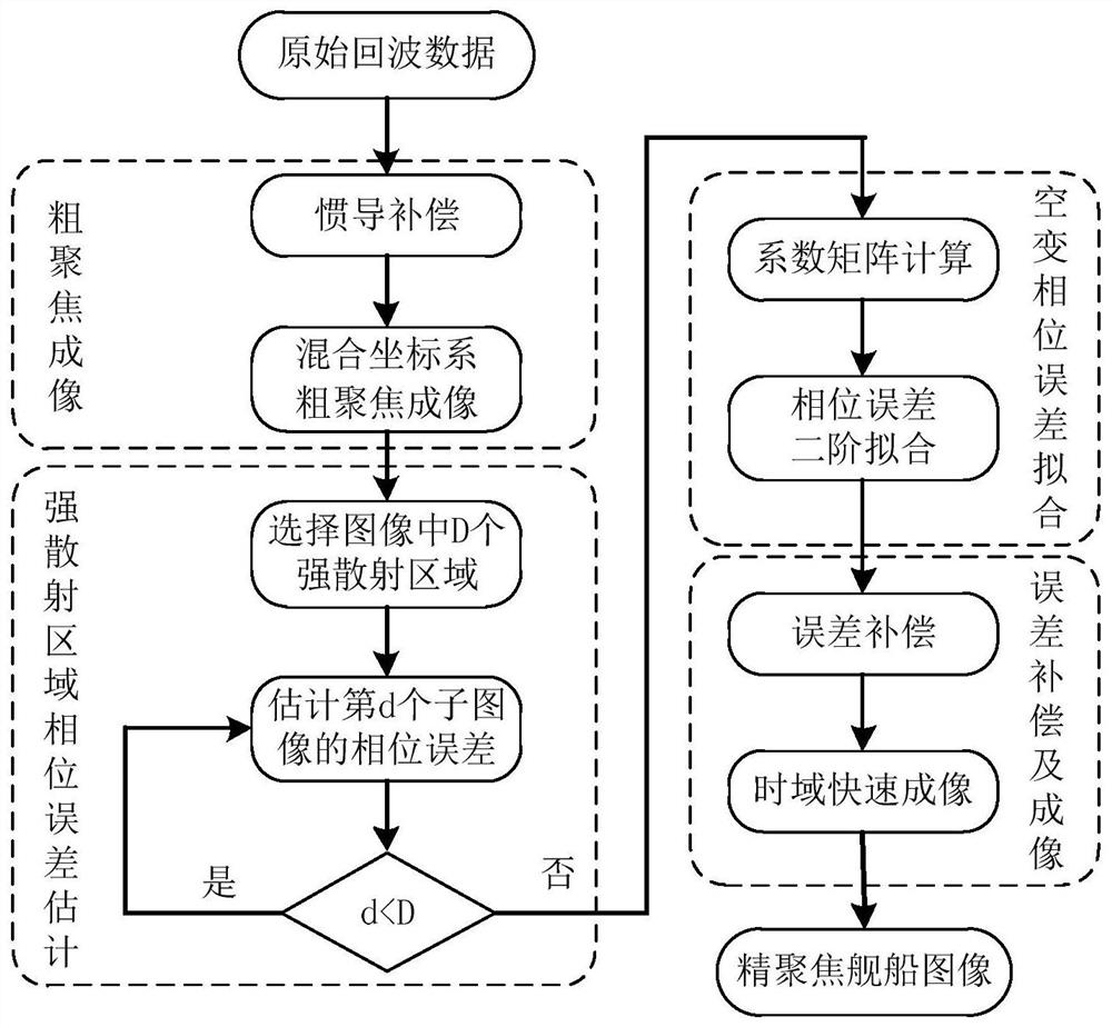
The invention discloses a self-focusing method for high-resolution moving ship SAR imaging. The method comprises the following steps: carrying out coarse compensation and range direction matched filtering processing on a baseband echo signal by adopting inertial navigation data; coarsely focusing the imaged original image; screening out a plurality of strong scattering regions from the original image, and respectively estimating a local phase error of each strong scattering region by using a weighted phase gradient self-focusing method; calculating a coefficient matrix of a second-order errorpolynomial; constructing coordinate vectors X and Y of the whole original image, and fitting a phase error of each pixel point at each slow moment by utilizing a coefficient matrix; and compensating the original image by adopting the phase error estimation matrix. According to the invention, the problem that a traditional self-focusing method cannot perform unified estimation compensation on space-variant phase errors caused by ship motion during moving ship imaging is solved, and accurate focusing of moving ship high-resolution imaging is achieved.

Description

technical field [0001] The invention relates to the technical field of synthetic aperture radar imaging, in particular to a self-focusing method for high-resolution moving ship SAR imaging. It can be used for self-focusing processing of moving ship imaging by airborne, missile-borne and other radar platforms. Background technique [0002] Synthetic Aperture Radar (SAR), as an active microwave active sensor, can obtain two-dimensional images of the observation scene all day, all day long and from a long distance, and has been widely used in various radar carriers. However, due to the movement of the ship within the beam irradiation time, the ship target in the SAR image will appear defocused; at the same time, with the improvement of the resolution, the pixel points occupied by the large ship target in the SAR image are getting smaller and smaller. However, the ups and downs of each part of the ship under the influence of wind and waves are different, which makes it difficul...

Claims


Application Information

Patent Timeline
IPC IPC(8): G01S13/90
CPCG01S13/9052G01S13/9029
Inventor 梁毅李国霏孙昆曾裕贵
Owner XIDIAN UNIV
Learn More