Single-hop broadcast control beam pointing method

A beam pointing and beam technology, applied in the field of fast single-hop broadcast control beam pointing, can solve the problems of poor network scalability, power reduction, consumption, etc., achieve low software and hardware resource requirements, improve the receiving signal-to-noise ratio, and increase scalability. sexual effect

Active Publication Date: 2021-10-15
10TH RES INST OF CETC
View PDF4 Cites 0 Cited by
  • Summary
  • Abstract
  • Description
  • Claims
  • Application Information

AI Technical Summary

Problems solved by technology

This method is very fast to achieve single-hop broadcasting, but this forwarding mechanism requires a lot of antenna or beam resources, and the cost of software and hardware is very high, and in the process of parallel transmission, often multiple beams need to equally share the power resources of the broadcast node , the power allocated to a single beam is greatly reduced, and there is usually mutual interference between the beams, the receiving signal-to-noise ratio of neighboring nodes is significantly reduced, which greatly reduces the reliability of single-hop broadcasting
Due to very limited antenna or beam resources, this method is only suitable for small networks with few nodes. For dense directional networks, when the number of neighbor nodes is large, for N neighbor nodes, N directional beam resources are required. None of the beam resources can bear
In addition, due to hardware limitations, the beam resources of nodes are limited, the network scalability in this way is poor, and it does not have the ability to adapt to network topology
[0009] To sum up, the existing technical solutions either rely on the stacking of software and hardware resources, or rely on extending the time for single-hop broadcasting of directional networks, which have their own limitations and cannot meet the needs of fast and reliable broadcasting in large-scale dense directional networks.

Method used


Image

  • Single-hop broadcast control beam pointing method
  • Single-hop broadcast control beam pointing method
  • Single-hop broadcast control beam pointing method

Examples


Embodiment Construction

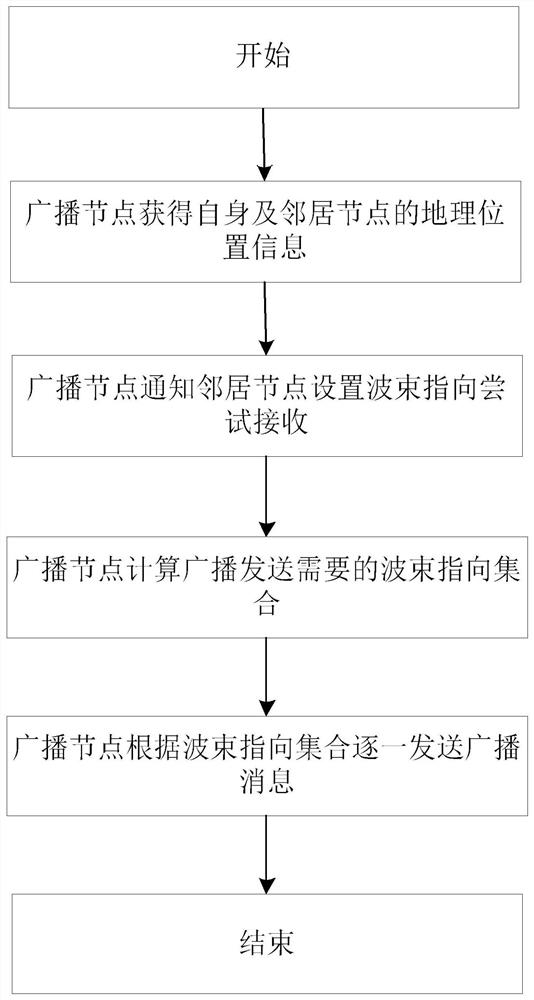
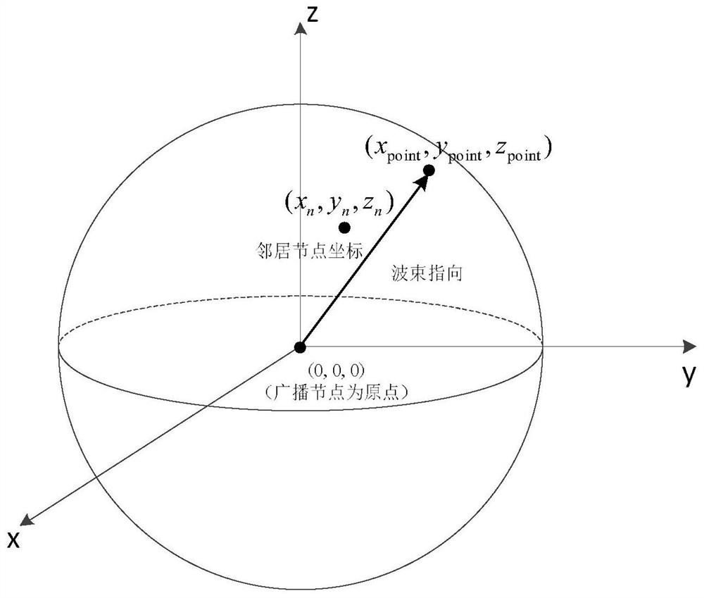
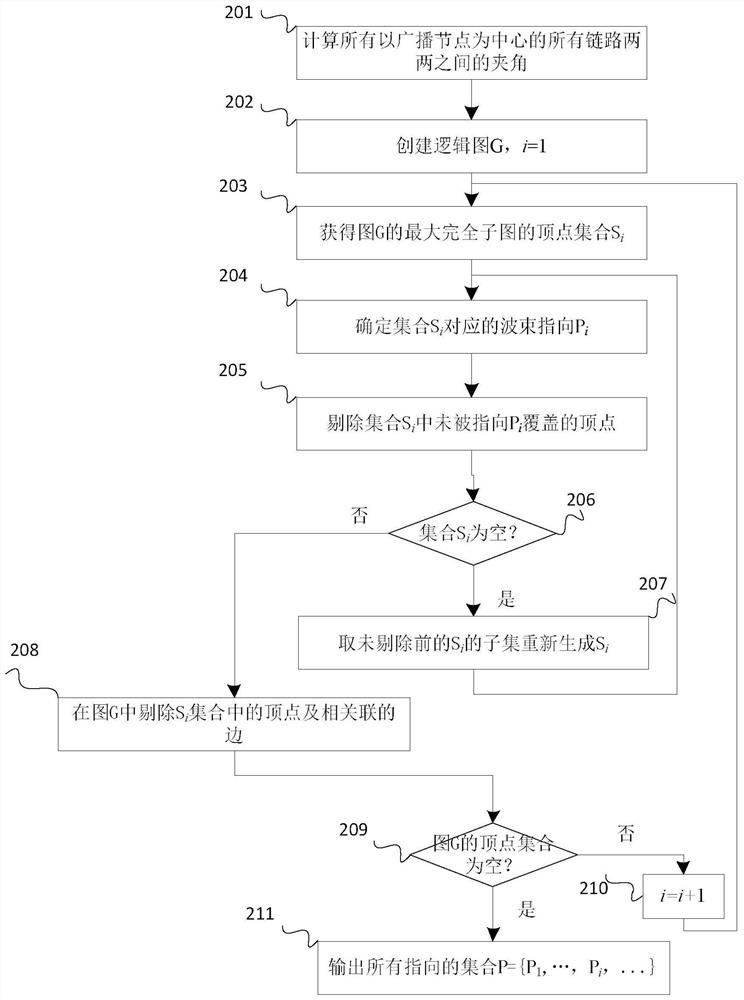
[0023] see figure 1 . According to the present invention, a single-hop broadcast control beam pointing method has the following technical features: in the directional network, in the directional network, the broadcast node obtains the geographic location information of itself and each neighbor node through GPS, and uses Send data with a single beam, notify all neighbor nodes to set the beam pointing and try to receive, and all other nodes schedule beam resources to point to the broadcast node to receive data; then, the broadcast node uses all geographical location information to calculate the beam pointing set required for broadcast transmission, and calculates Find the included angles between all pairs of links, create a logical graph G, and find the largest complete subgraph in the logical graph G to calculate the beam pointing, and use the largest complete subgraph to determine the beam pointing P i ; During a single beamforming transmission process, broadcast messages ar...


PUM


Abstract

The invention discloses a single-hop broadcast control beam pointing method, aiming to provide a method with high broadcast efficiency and low broadcast time delay. And it is realized through the following technical scheme: In the directional network, the broadcast node obtains the geographical location information of itself and each neighbor node through GPS, uses a single beam to send data in the fast broadcast, and notifies all neighbor nodes to set the beam pointing and try to receive, all The remaining nodes schedule beam resources to point to the broadcast node to receive data; then, the broadcast node uses all geographical location information to calculate the beam pointing set required for broadcast transmission, calculates the angle between all pairs of links, and creates a logic graph G, And find the largest complete subgraph in the logic graph G to calculate the beam pointing, and use the largest complete subgraph to determine the beam pointing P i ; During a single beamforming transmission process, broadcast messages are sent one by one according to the beam pointing set until all the beam pointing in the beam set are processed.

Description

technical field [0001] The invention relates to a fast single-hop broadcast control beam pointing method suitable for directional networks. Background technique [0002] The antenna has different radiation or receiving capabilities for different directions in space, which is the directivity of the antenna. According to different directions, communication antennas used in wireless networks are generally divided into two categories: omnidirectional antennas and directional antennas. Omnidirectional antennas refer to non-directionality, which is shown as uniform radiation in the whole range on the pattern. A directional antenna refers to a directional antenna that radiates within a certain angle range on the pattern. Compared with omnidirectional antennas, directional antennas have many advantages such as high gain, long transmission distance, high speed, and good anti-interference performance, and are more and more widely used in wireless communication networks. [0003] A ...

Claims


Application Information

Patent Timeline
Patent Type & Authority Patents(China)
IPC IPC(8): H04W4/06H04W16/28H04W28/02H04B7/06
CPCH04B7/0617H04W4/06H04W16/28H04W28/0289
Inventor 王昭钮金鑫
Owner 10TH RES INST OF CETC
Why Eureka
Try Eureka