
Crushing type medical intravenous infusion tube recycling machine

An intravenous infusion, pulverized technology, applied in the field of pulverized medical intravenous infusion tube recycling machines, can solve the problems of large occupied space, easy slipping of medical staff and patients, and influence of walking of medical staff and patients, etc., and achieves the effect of reducing the occupied space.

Inactive Publication Date: 2020-11-06
韩象勇
View PDF9 Cites 2 Cited by
  • Summary
  • Abstract
  • Description
  • Claims
  • Application Information

AI Technical Summary

Problems solved by technology

[0002] Now the intravenous infusion tubes used in hospitals are generally disposable, and the used intravenous infusion tubes are generally thrown directly into the trash can, and the intravenous infusion tubes are longer, so the space occupied by the intravenous infusion tubes is larger, so the intravenous infusion tubes It is easy to fall from the trash can to the ground, which will affect the walking of medical staff or patients, and there is generally residual medicinal liquid in the intravenous infusion tube, so when the intravenous infusion tube falls to the ground, the medicinal liquid in it will It is easy to flow out and fall on the ground to wet the ground, so that medical staff or patients are easy to slip and fall while walking

Method used


Image

  • Crushing type medical intravenous infusion tube recycling machine
  • Crushing type medical intravenous infusion tube recycling machine
  • Crushing type medical intravenous infusion tube recycling machine

Examples


Embodiment 1

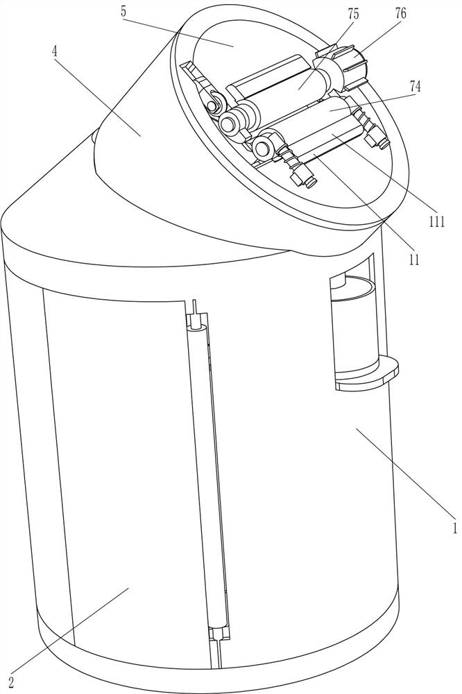
[0023] A crushing type medical venous infusion tube recovery machine, such as Figure 1-5 As shown, it includes a placement tube 1, a hinged plate 2, a collection frame 3, a mounting pipe 4, a mounting plate 5, a hopper 6, a feeding mechanism 7 and a cutting mechanism 8, and the front part of the placement tube 1 is hingedly connected with a hinged plate 2. A collection frame 3 is placed inside the tube 1, and the top of the tube 1 is embedded with an installation tube 4, the bottom left side of the installation tube 4 is connected with a discharge hopper 6, the top of the installation tube 4 is connected with an installation plate 5, and the top of the installation plate 5 is installed with a feeding Mechanism 7, a cutting mechanism 8 is installed on the bottom of the mounting plate 5, and the feeding mechanism 7 is connected with the cutting mechanism 8 through transmission.

[0024] The feeding mechanism 7 includes a sliding sleeve 71, a slide bar 72, a first spring 73, a f...

Embodiment 2

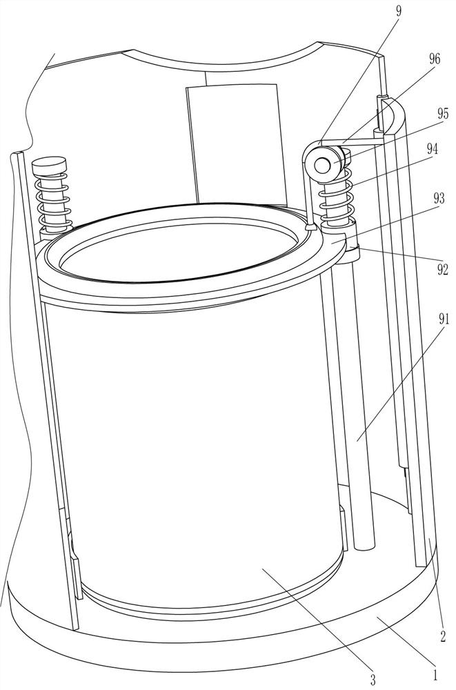
[0028] On the basis of Example 1, such as figure 2 Shown, also comprise pocket pressing mechanism 9, and pocket pressing mechanism 9 comprises vertical bar 91, guide ring 92, pressure ring 93, the 3rd spring 94, guide wheel 95 and stay cord 96, collection frame 3 front and back Both sides are placed in the top of the tube 1 and are connected with a vertical rod 91, and a guide ring 92 is slidably connected to the vertical rod 91, and a pressure ring 93 is connected between the two guide rings 92, and the top of the guide ring 92 is connected with the top of the vertical rod 91. The third spring 94 is connected therebetween, the top of the front side vertical bar 91 is rotatably connected with a guide wheel 95, the top of the pressure ring 93 is connected with a stay cord 96, and the top of the stay cord 96 goes around the guide wheel 95 and is connected to the inner side of the hinge plate 2.

[0029] When the hinged plate 2 is opened, the pull cord 96 can pull the pressure r...

Embodiment 3

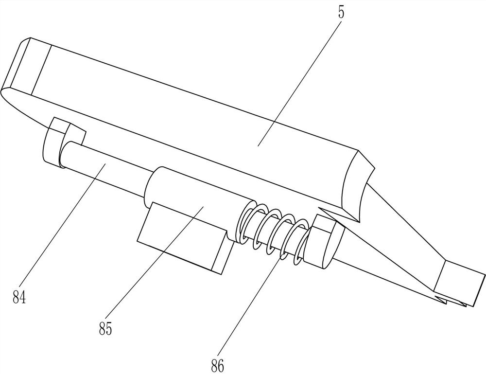
[0031] On the basis of Example 2, such as image 3 As shown, it also includes a waste liquid collection mechanism 10. The waste liquid collection mechanism 10 includes a liquid collection cup 101, a grid plate 102, a liquid outlet bucket 103 and a placement plate 104. There is a port on the right side of the placement cylinder 1. Slidingly connected with a placement plate 104, the top of the placement plate 104 is connected with a liquid collection cup 101, the right side of the discharge hopper 6 is connected with a grid plate 102, the right side of the grid plate 102 is connected with a liquid outlet 103, and the liquid outlet 103 Located on the upper side of the liquid collection cup 101.

[0032] The residual medical solution in the intravenous infusion tube flows into the outlet hopper 103 through the grid plate 102, and the residual medical solution in the outlet hopper 103 then flows into the liquid collection cup 101, so that the residual medical solution can be collec...


PUM


Abstract

The invention relates to a medical intravenous infusion tube recycling machine, in particular to a crushing type medical intravenous infusion tube recycling machine. The crushing type medical intravenous infusion tube recycling machine is capable of reducing occupied space of an intravenous infusion tube and collecting residual medicine liquid. In order to solve the technical problem, the crushingtype medical intravenous infusion tube recycling machine comprises a placing cylinder, a collecting frame, a mounting pipe, a discharging hopper, a mounting disc and a material conveying mechanism, wherein a hinge plate is hinged to one side of the placing cylinder, the collecting frame is arranged in the placing cylinder, the placing cylinder is connected to the mounting pipe, one end of the mounting pipe is connected to the discharging hopper, the other end of the mounting pipe is connected to the mounting disc, and one end of the mounting disc is provided with the material conveying mechanism. The material conveying mechanism of the machine can enable the intravenous infusion tube to enter the mounting pipe, a cutting mechanism can shear the intravenous infusion tube entering the mounting pipe, and the intravenous infusion tube can be cut into small sections.

Description

technical field [0001] The invention relates to a recycling machine for medical venous transfusion tubes, in particular to a crushing type recycling machine for medical venous transfusion tubes. Background technique [0002] Now the intravenous infusion tubes used in hospitals are generally disposable, and the used intravenous infusion tubes are generally thrown directly into the trash can, and the intravenous infusion tubes are longer, so the space occupied by the intravenous infusion tubes is larger, so the intravenous infusion tubes It is easy to fall from the trash can to the ground, which will affect the walking of medical staff or patients, and there is generally residual medicinal liquid in the intravenous infusion tube, so when the intravenous infusion tube falls to the ground, the medicinal liquid in it will It is easy to flow out and fall on the ground to wet the ground, so that medical staff or patients are easy to slip and fall while walking. [0003] Therefore ...

Claims


Application Information

Patent Timeline
Patent Type & Authority Applications(China)
IPC IPC(8): B09B3/00B26D1/08B26D5/16B65F1/06B65F1/16
CPCB09B3/0075B26D1/08B26D5/16B65F1/06B65F1/1646B65F2210/126
Inventor 韩象勇
Owner 韩象勇
Learn More