Cutting blade and cutting tool
A cutting insert and cutting tool technology, applied in milling cutters, manufacturing tools, metal processing equipment, etc., can solve problems affecting life stability, residual stress, etc., to increase cutting life, reduce cutting resistance, and reduce cutting power. effect of demand
- Summary
- Abstract
- Description
- Claims
- Application Information
AI Technical Summary
Problems solved by technology
Method used
Image

Examples
Embodiment 1
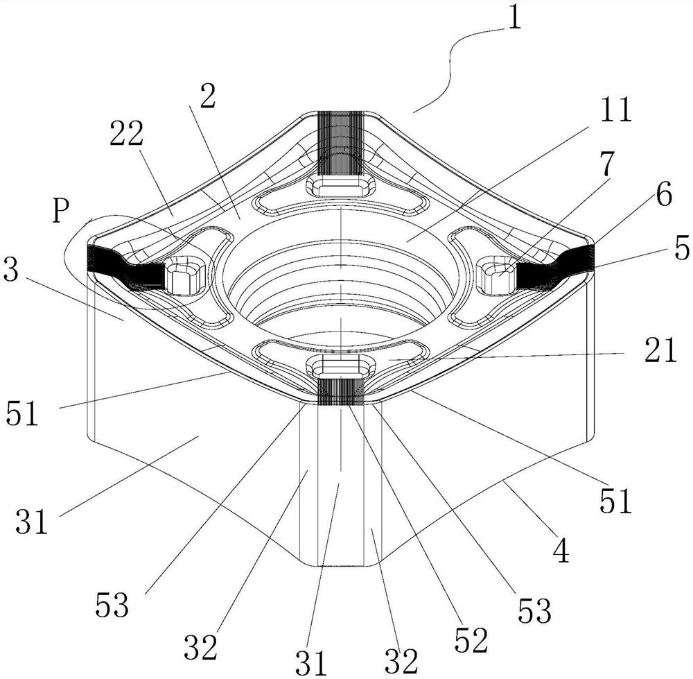
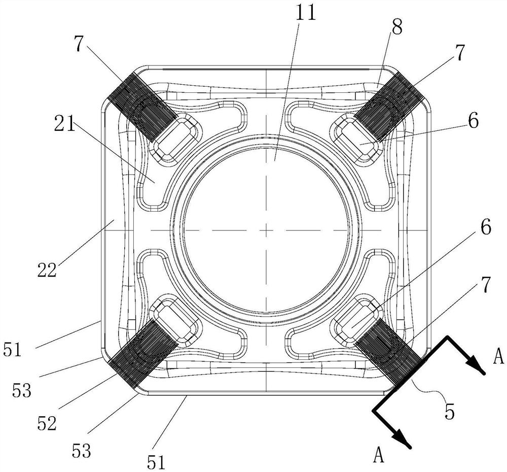
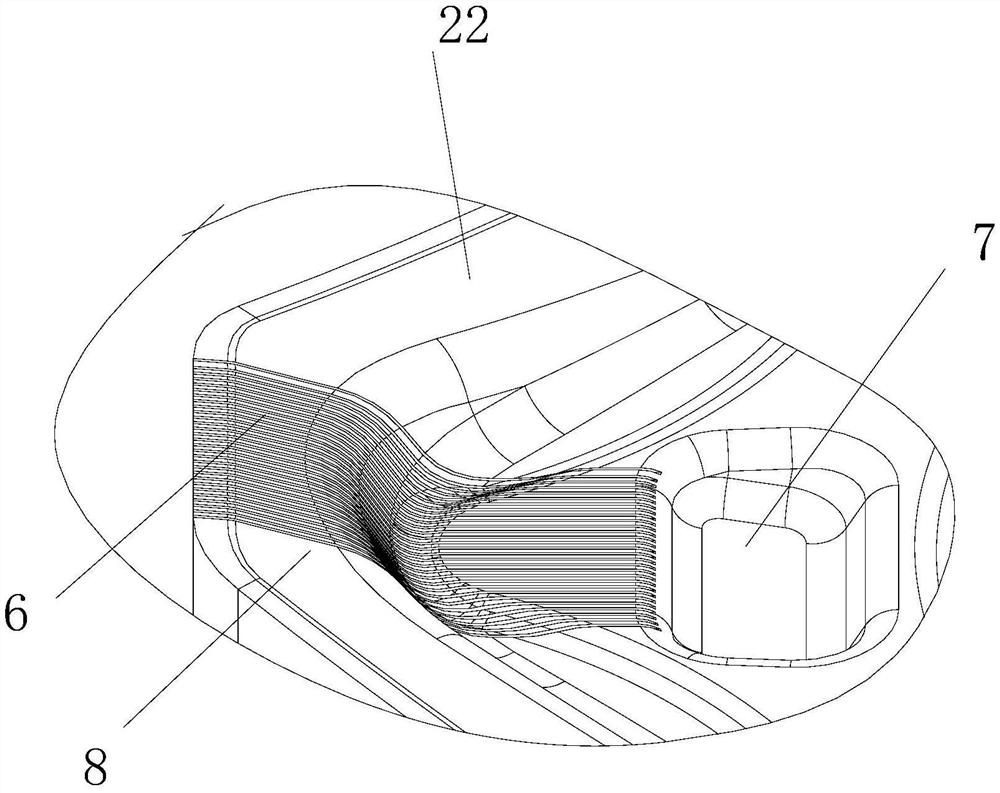
[0034] Such as Figure 1 to Figure 4 As shown, the cutting blade of this embodiment includes a blade body 1, the blade body 1 includes an upper surface 2, a lower surface 4 and a plurality of side surfaces 3 arranged between the upper surface 2 and the lower surface 4, and the blade body 1 is provided with at least A group of cutting units 5, the cutting unit 5 is located between any two adjacent sides 3, the upper surface 2 intersects with the two adjacent sides 3 to form a main cutting edge 51, the main cutting edge 51 constitutes the cutting unit 5, the blade The position of the main body 1 corresponding to the cutting unit 5 is provided with a lyophobic guide surface 6 and a lyophilic groove 7. The lyophilic groove 7 is arranged in the upper surface 2, and the lyophobic guide surface 6 is arranged between the cutting unit 5 and the lyophilic groove 7. The liquid guide surface 6 has a surface texture that can reduce surface friction.
[0035] Studies have shown that the sm...
Embodiment 2
[0051] Such as Figure 6 As shown, the cutting tool of the present embodiment includes a cutter body 9, and also includes the cutting blade in Embodiment 1. The cutter body 9 is provided with a plurality of sipes 91 along the circumference, and a cutting blade is installed in each sipe 91, and the sipes 91 includes a groove bottom surface 901 and two groove positioning sides 902, the lower surface 4 of the blade body 1 is in contact with the groove bottom surface 901, the two adjacent sides 3 of the blade body 1 are in contact with the two groove positioning sides 902, and the knife groove 91 is provided with The cooling hole 92 faces the lyophilic groove 7 of the blade body 1 .
[0052] In this embodiment, the cutter body 9 rotates clockwise around the center line O in the direction of rotation, or it is called right-handed in the industry, and includes the same number of sipes 91 as the number of cutting blades. In this embodiment, the number of blades and sipes 91 is 16. i...
Embodiment 3
[0057] Such as Figure 7 to Figure 9 As shown, the cutting insert of this embodiment differs from Embodiment 1 only in that:
[0058] In this embodiment, the blade body 1 has a regular heptagonal structure. A second transition arc side 34 is provided between the adjacent two side faces 3 corresponding to the cutting unit 5, and the second transition arc side 34 and the side faces 3 on both sides are connected by a second straight side 35, and the upper surface 2 and the The second transition arc side surface 34 intersects to form a second transition cutting edge 54, and the upper surface 2 intersects with the second straight side surface 35 to form a second cutting straight edge 55. The second transition cutting edge 54, two second cutting straight edges 55 and two Each main cutting edge 51 constitutes a group of cutting units 5 . The second straight cutting edge 55 plays a smoothing effect. The second transitional cutting edge 54 is smoothly connected with two second strai...
PUM
 Abstract
Description
Claims
Application Information
 - R&D
- Intellectual Property
- Life Sciences
- Materials
- Tech Scout
- Unparalleled Data Quality
- Higher Quality Content
- 60% Fewer Hallucinations
Browse by: Latest US Patents, China's latest patents, Technical Efficacy Thesaurus, Application Domain, Technology Topic, Popular Technical Reports.
© 2025 PatSnap. All rights reserved.Legal|Privacy policy|Modern Slavery Act Transparency Statement|Sitemap|About US| Contact US: help@patsnap.com