
A laser engraving equipment for mobile phone antenna processing

A mobile phone antenna and laser engraving technology, which is applied to metal processing equipment, antennas, welding equipment, etc., can solve problems such as eye injury, processing deviation, and easily burnt operators of molded parts

Active Publication Date: 2022-01-11
深圳市拓频物联技术有限公司
View PDF0 Cites 0 Cited by
  • Summary
  • Abstract
  • Description
  • Claims
  • Application Information

AI Technical Summary

Problems solved by technology

[0004] The purpose of the present invention is to solve the shortcomings of the existing laser radium engraving technology, which is inconvenient to use and hurts the eyes, and there is no certain fixing device, which is easy to cause processing deviation, and it is easy to burn the operator when the molded parts are not cooled well. A laser engraving equipment for mobile phone antenna processing proposed

Method used


Image

  • A laser engraving equipment for mobile phone antenna processing
  • A laser engraving equipment for mobile phone antenna processing
  • A laser engraving equipment for mobile phone antenna processing

Examples


Embodiment 1

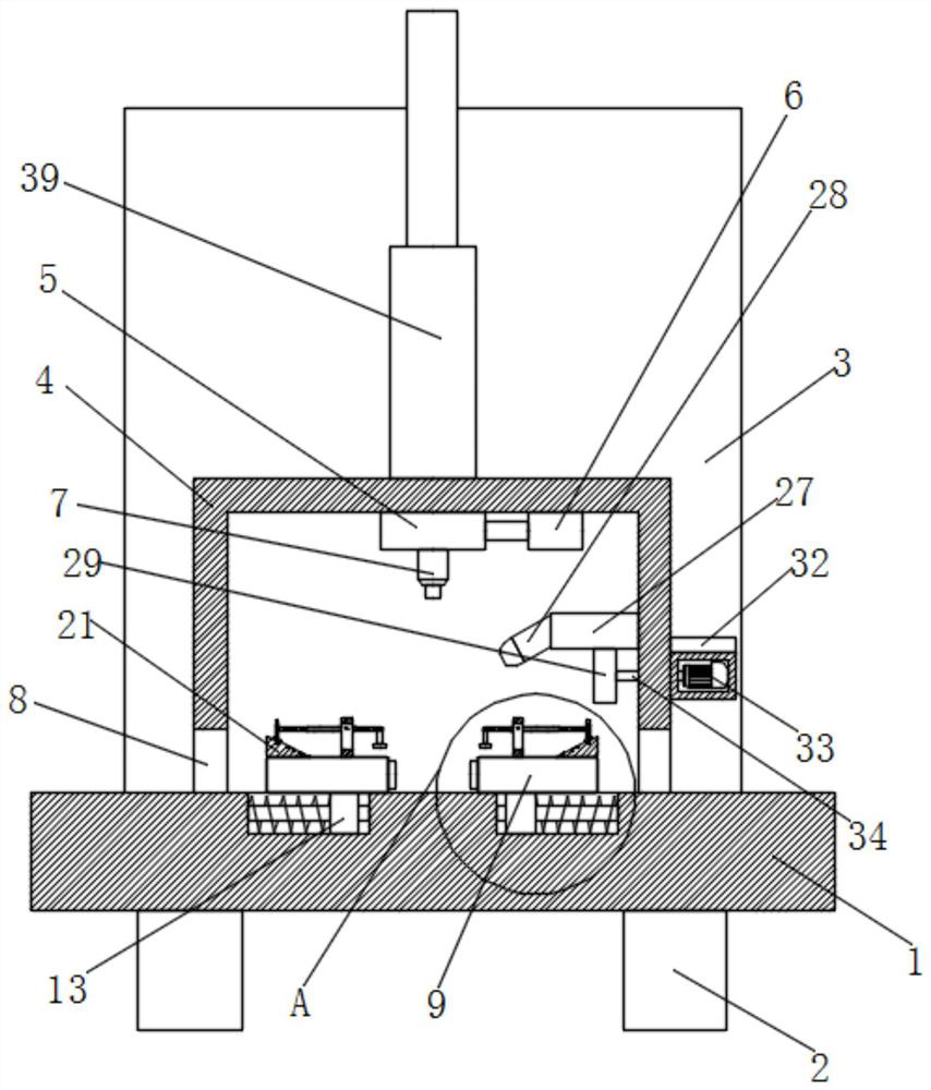
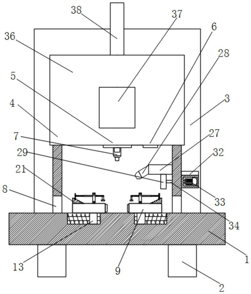
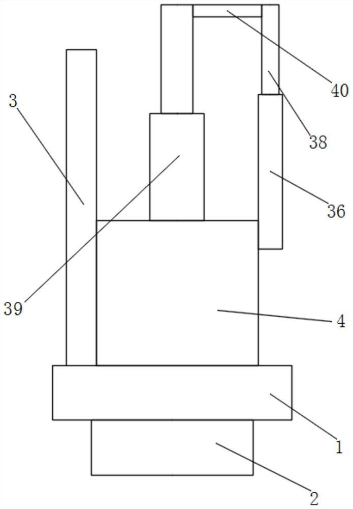
[0029] refer to Figure 1-6 , a laser engraving device for mobile phone antenna processing, comprising a base plate 1, two brackets 2 are symmetrically fixedly installed on the bottom of the base plate 1, side plates 3 are fixedly installed on the top of the base plate 1, and a protective cover is fixedly installed on the top of the base plate 1 4. A control box 5 is slidably installed on the top inner wall of the protective cover 4, a laser processing head 7 is movably installed on the bottom of the control box 5, and a first electric push rod 6 is fixedly installed on the top inner wall of the protective cover 4. The output shaft of the rod 6 is fixedly connected with the control box 5, and the protective cover 4 is symmetrically provided with two through holes 8, and the top of the bottom plate 1 is slidably mounted with two splints 9, the two splints 9 are matched, and the two splints 9 The first connecting plate 18 is movably installed on the top, the bottom of the two fi...

Embodiment 2

[0040] refer to Figure 1-6 , a laser engraving device for mobile phone antenna processing, including a base plate 1, the bottom of the base plate 1 is symmetrically fixed with two brackets 2 by welding, the top of the base plate 1 is fixedly installed with a side plate 3 by welding, and the top of the base plate 1 is fixed by welding. A protective cover 4 is fixedly installed by welding, a control box 5 is slidably installed on the top inner wall of the protective cover 4, a laser processing head 7 is movably installed on the bottom of the control box 5, and a first electric motor is installed on the top inner wall of the protective cover 4 by screws. Push rod 6, the output shaft of the first electric push rod 6 is fixedly connected with the control box 5, two through holes 8 are symmetrically opened on the protective cover 4, and two splints 9 are symmetrically slidably installed on the top of the bottom plate 1, and the two splints 9 Matched, the tops of the two splints 9 a...


PUM


Abstract

The invention belongs to the technical field of production and processing of mobile phone accessories, in particular a radium engraving device for mobile phone antenna processing, which is inconvenient to use and hurts the eyes in view of the existing laser radium engraving technology, and there is no fixed device, which easily causes processing deviation , and there is no problem that it is easy to burn the operator when the cooled molded parts are processed, the following scheme is proposed now, which includes a bottom plate, two brackets are fixedly fixed symmetrically on the bottom of the bottom plate, side plates are fixedly installed on the top of the bottom plate, and the bottom of the bottom plate A protective cover is fixedly installed on the top, a control box is slidably installed on the inner wall of the top of the protective cover, and a laser processing head is movably installed at the bottom of the control box. The invention can fix the antenna of the mobile phone during processing and keep it stable, ensuring that there will be no deviation in the processing process and ensuring the processing quality, and the device has a certain protection device, which greatly reduces and avoids the problems during the processing and at the end of the processing. injury to the operator.

Description

technical field [0001] The invention relates to the technical field of production and processing of mobile phone accessories, in particular to a laser engraving device used for processing mobile phone antennas. Background technique [0002] In the current society, mobile phones have become an indispensable part of daily life, and the manufacturing process of mobile phones is becoming more and more complicated. Among them, the processing and manufacturing of mobile phone antennas requires the use of laser engraving technology; laser engraving is also called laser engraving. Principle The process of surface treatment, which uses the high-intensity focused laser beam emitted by the laser at the focal point, evaporates the surface material to expose the deep material; or causes the chemical and physical changes of the surface material to leave traces through light energy; or burns it away through light energy Part of the material, and "engraved" traces; or burn part of the mater...

Claims


Application Information

Patent Timeline
Patent Type & Authority Patents(China)
IPC IPC(8): B23K26/03B23K26/08B23K26/362B23K26/70H01Q1/24
CPCB23K26/703B23K26/706B23K26/362B23K26/03B23K26/08H01Q1/242
Inventor 戴梓峰李东海
Owner 深圳市拓频物联技术有限公司
Learn More