Magnetic ferrite core forming equipment feeding device

A technology of magnetic ferrite and molding equipment, applied in mixers with rotating stirring devices, packaging, transportation and packaging, etc., can solve the problems of low efficiency and manpower consumption, and achieve the guarantee of preparation quality, good cutting effect, well-designed effects

Active Publication Date: 2020-11-06
天长市烁源磁电有限公司
View PDF11 Cites 1 Cited by
  • Summary
  • Abstract
  • Description
  • Claims
  • Application Information

AI Technical Summary

Problems solved by technology

[0005] The purpose of the present invention is to solve the problem of labor-intensive and low efficiency in the prior art, and propose a feeding device for magnetic ferrite core forming equipment

Method used


Image

  • Magnetic ferrite core forming equipment feeding device
  • Magnetic ferrite core forming equipment feeding device
  • Magnetic ferrite core forming equipment feeding device

Examples


Embodiment 1

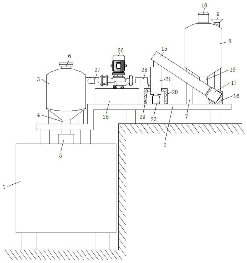
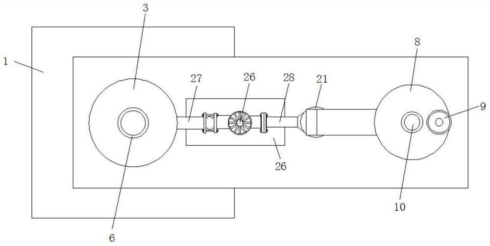
[0027] refer to Figure 1-4 , a magnetic ferrite core molding equipment feeding device, comprising a molding equipment body 1, the feeding end of the molding equipment body 1 is fixed with a feeding pipe 5, the upper end of the molding equipment body 1 is provided with a mounting frame 2, and the mounting frame 2 One side of the top surface is fixed with a cyclone collector 3, the output end of the cyclone collector 3 is fixed with a feeding pipe 4, the lower end of the feeding pipe 4 is placed in the feeding pipe 5, and the top of the cyclone collector 3 is also fixed with an exhaust pipe 6, The other side of the top surface of the mounting frame 2 is also fixed with a support seat 7, the top of the support seat 7 is fixed with a storage barrel 8 by screws, and the upper end of the storage barrel 8 is connected with a feed funnel 9 through one side, and the center of the top surface of the storage barrel 8 The position is also fixed with a servo motor-10 by screws, the output...

Embodiment 2

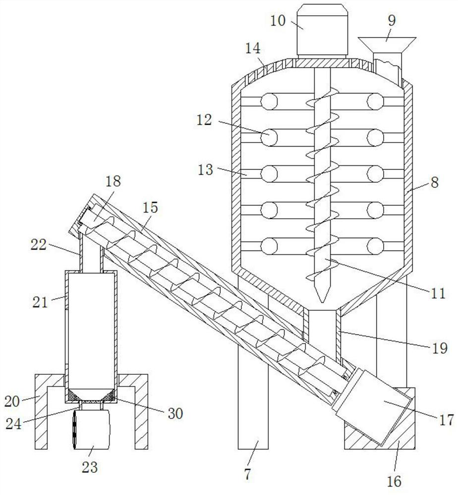
[0030] Such as image 3 with 4 As shown, this embodiment is basically the same as Embodiment 1. Preferably, the inner bottom surface of the lower material barrel 21 is also fixedly connected with a retaining column 30, and the top surface of the retaining column 30 is provided with a conical hole, and the upper end of the air inlet pipe 24 is fixedly connected to On the lower inner wall of the tapered hole.

[0031] In this embodiment, the retaining column 30 is fixedly connected to the inner bottom surface of the lower material barrel 21, so as to prevent the powder from accumulating on both sides of the bottom surface of the lower material barrel 21, and ensure that the blower 23 can realize the blowing of all the key powder materials, so that the powder material The cutting effect is better.

Embodiment 3

[0033] Such as figure 1As shown, this embodiment is basically the same as Embodiment 1. Preferably, the molding equipment body 1 is fixed on the working surface, and the two sides of the mounting frame 2 are respectively fixed on the top surface of the molding equipment body 1 and the working surface by screws.

[0034] In this embodiment, by fixing the installation frame 2 on the top surface and the working surface of the molding equipment body 1, the operation of the device is made more stable, and the service life of the device is well extended.


PUM


Abstract

The invention discloses a magnetic ferrite core forming equipment feeding device. The magnetic ferrite core forming equipment feeding device comprises a forming equipment body, a material injection pipe is fixed to the feeding end of the forming equipment body, a mounting frame is arranged at the upper end of the forming equipment body, a cyclone collector is fixed to one side of the top face of the mounting frame, a feeding pipe is fixed to the output end of the cyclone collector, the lower end of the feeding pipe is arranged in the material injection pipe, an exhaust pipe is further fixed tothe top of the cyclone collector, a supporting base is further fixed to the other side of the top face of the mounting frame, a storage barrel is fixed to the top of the supporting base through screws, a feeding hopper is connected to one side of the upper end of the storage barrel in a penetrating mode, and a first servo motor is further fixed to the center of the top face of the storage barrelthrough screws. The device is reasonable in design, the loading operation of ferrite core forming is realized by adopting a negative pressure adsorption mode, the powder quality is good, the influenceof caking in the powder on the production quality of the ferrite core is avoided, and the preparation quality of the ferrite core is well ensured.

Description

technical field [0001] The invention relates to the technical field of magnetic ferrite production equipment, in particular to a feeding device for magnetic ferrite core forming equipment. Background technique [0002] Ferrite core is a high-frequency magnetic material, mainly used for high-frequency transformers, high-frequency magnetic rings, etc., to increase the magnetic permeability and improve the quality factor of inductance. It is used in transformers, and ferrite cores are mostly made of die-casting molding technology. , using high temperature melting. [0003] After retrieval, the patent application number 201921447073.X discloses a ferrite core forming device, which includes a main body and a discharge pipe. The pipe is arranged in the middle of the bottom end of the silo, and the bottom of the silo is provided with a partition, and the bottom of the partition is provided with a telescopic mechanism, and the inner side of the outer wall of the telescopic mechanis...

Claims


Application Information

Patent Timeline
IPC IPC(8): B65G33/14B65G33/24B65G33/26B65G53/14B65G53/34B65G53/36B65G65/46B01F7/24
CPCB65G33/14B65G33/24B65G33/265B65G65/46B65G53/14B65G53/34B65G53/36B01F27/92
Inventor 沈桂良张惠明
Owner 天长市烁源磁电有限公司
Why Eureka
Try Eureka