Method of producing carbon material
A material and coke tower technology, applied in the production of carbon materials, can solve the problems of high thermal expansion system and unstable needle coke streamlined texture, so as to increase product yield, reduce isotropic coke production, and improve product quality.
- Summary
- Abstract
- Description
- Claims
- Application Information
AI Technical Summary
Problems solved by technology
Method used
Image
Examples
Embodiment 1
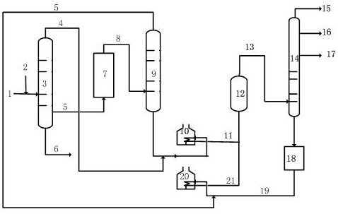
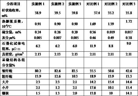
[0033] Catalytic oil slurry from a refinery was used as raw material, and the specific properties of the oil slurry are shown in Table 1. The temperature of the 10% distillation point of the vacuum residue is 500°C, the mass ratio of the catalytic oil slurry to the vacuum residue is 1:0.3, and the temperature of the 10% distillation point of the light distillate oil on the third tower of the vacuum deep drawing device is 220°C. The temperature of the 90% distillation point is 310°C, the 10% distillation point of the middle distillate is 320°C, the 90% distillation point is 450°C, and the 10% distillation point of the bottom heavy distillate is 460°C. The middle distillate oil enters the hydrotreating unit 7 through the pipeline 5, and the catalyst bed of the hydrotreating unit is filled as follows: a total of four reactors of the unit are respectively filled with a protective agent, a metal removal agent, a desulfurizer and a denitrification agent, and the filling volume ratio ...
Embodiment 2
[0035] Catalytic oil slurry from a refinery was used as raw material, and the specific properties of the oil slurry are shown in Table 1. The temperature of the 10% distillation point of the vacuum residue is 530°C, the mass ratio of the catalytic oil slurry to the vacuum residue is 1:0.6, and the temperature of the 10% distillation point of the light distillate oil on the third column of the vacuum deep drawing device is 230°C. The temperature of the 90% distillation point is 350°C, the 10% distillation point of the middle distillate is 360°C, the 90% distillation point is 480°C, and the 10% distillation point of the bottom heavy distillate is 490°C. The middle distillate oil enters the hydrotreating unit 7 through the pipeline 5, and the catalyst bed of the hydrotreating unit is filled as follows: a total of four reactors of the unit are respectively filled with a protective agent, a metal removal agent, a desulfurizer and a denitrification agent, and the filling volume ratio...
Embodiment 3
[0037] Catalytic oil slurry from a refinery was used as raw material, and the specific properties of the oil slurry are shown in Table 1. The temperature of the 10% distillation point of the vacuum residue is 540°C, the mass ratio of the catalytic oil slurry to the vacuum residue is 1:1, and the temperature of the 10% distillation point of the light distillate on the third tower of the vacuum deep drawing device is 240°C. The temperature of the 90% distillation point is 380°C, the 10% distillation point of the middle distillate is 390°C, the 90% distillation point is 490°C, and the 10% distillation point of the bottom heavy distillate is 500°C. The middle distillate oil enters the hydrotreating unit 7 through the pipeline 5, and the catalyst bed of the hydrotreating unit is filled as follows: a total of four reactors of the unit are respectively filled with a protective agent, a metal removal agent, a desulfurizer and a denitrification agent, and the filling volume ratio is 5:...
PUM
 Abstract
Description
Claims
Application Information
 - R&D
- Intellectual Property
- Life Sciences
- Materials
- Tech Scout
- Unparalleled Data Quality
- Higher Quality Content
- 60% Fewer Hallucinations
Browse by: Latest US Patents, China's latest patents, Technical Efficacy Thesaurus, Application Domain, Technology Topic, Popular Technical Reports.
© 2025 PatSnap. All rights reserved.Legal|Privacy policy|Modern Slavery Act Transparency Statement|Sitemap|About US| Contact US: help@patsnap.com


