Prefabricated external wall component for passive house, connection structure and construction method

A passive house and exterior wall technology, applied to building components, walls, building structures, etc., can solve the problems of no wall reinforcement connection structure, improvement of assembly construction efficiency, etc., to improve waterproof effect, increase concrete area, and improve connection The effect of intensity

Pending Publication Date: 2020-11-06
CHENGDE GREEN BUILDING ENERGY SAVING TECH CO LTD
View PDF1 Cites 2 Cited by
  • Summary
  • Abstract
  • Description
  • Claims
  • Application Information

AI Technical Summary

Problems solved by technology

However, such passive walls only consider how to optimize the insulation layer material of the wall during technical improvement, and have not made improvements in the reinforcement connection structure of the wall, assembly construction efficiency, etc.

Method used


Image

  • Prefabricated external wall component for passive house, connection structure and construction method
  • Prefabricated external wall component for passive house, connection structure and construction method
  • Prefabricated external wall component for passive house, connection structure and construction method

Examples


Embodiment 1

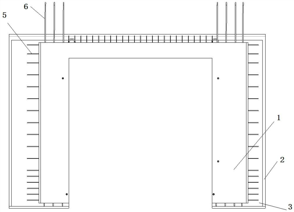
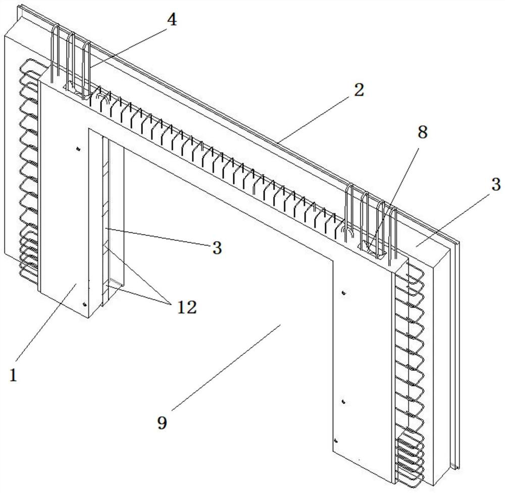
[0078] combine Figure 1-18 , in the present embodiment, a part of the outer leaf wall 2 protrudes toward the direction of the inner leaf wall 1, forming an anti-edge 11, that is, a part of the outer leaf wall 2 is thicker than its surroundings. Correspondingly, the insulation layer 3 between the anti-edge 11 and the inner leaf wall 1 is thinner relative to the insulation layer 3 of the rest.

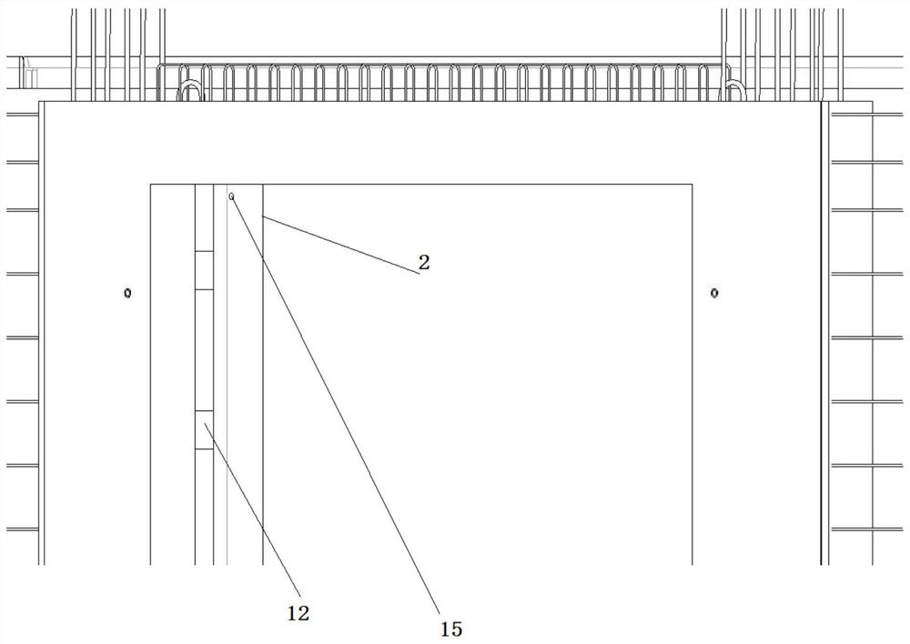
[0079] The hole 9 that is used to install door and window is from outer leaf wall 2, passes through inner leaf wall 1 through anti-edge 11, thermal insulation layer 3. A fixing component is provided at the insulation layer 3 between the anti-edge 11 and the inner leaf wall 1 for installing doors and windows. In some embodiments, the fixing part can be wooden bricks 12 embedded in the thermal insulation layer 3, the number of wooden bricks 12 is multiple, arranged at intervals along the thermal insulation board, the surface of the wooden bricks 12 is exposed on the inner edge of the hol...

Embodiment 2

[0090] The difference between this embodiment and embodiment 1 is:

[0091] combine Figure 19-27 , a part of the inner leaf wall 1 and a part of the outer leaf wall 2 protrude toward each other, forming two anti-edges 11, and between the two anti-edges 11 is the insulation layer 3, which is thinner than other parts, correspondingly Ground, the inner leaf wall 1 and the outer leaf wall 2 are thicker at the part along the anti-edge 11 than other parts. The fixing part that is used to install door and window is arranged between two anti-edges 11, and correspondingly, door and window is also installed in the part between two anti-edges 11. That is, the door and window are located in the middle part between the outer leaf wall 2 and the inner leaf wall 1 . Fixing part can adopt wooden brick 12 or subframe among the embodiment 1.

[0092]On the other hand, the longitudinal steel bars 4 are exposed in the cast-in-place cavity 6, specifically, a number of exposed rib grooves 13 ar...

Embodiment 3

[0094] The difference between this embodiment and embodiment 1 is:

[0095] combine Figure 28-37 , a part of the inner leaf wall 1 protrudes toward the outer leaf wall 2 to form an anti-edge 11, that is, a part of the inner leaf wall 1 is thicker than its surroundings. Correspondingly, the insulation layer 3 between the anti-edge 11 and the outer leaf wall 2 will be thinner relative to the insulation layer 3 of the rest.

[0096] The hole 9 that is used to install door and window is from inner leaf wall 1, passes through anti-edge 11, insulation layer 3, and runs through outer leaf wall 2. A fixing part is provided at the insulation board between the anti-edge 11 and the outer leaf wall 2 for installing doors and windows. In some embodiments, the fixing part can be wooden bricks 12 embedded in the thermal insulation layer 3, the number of wooden bricks 12 is multiple, arranged at intervals along the thermal insulation board, the surface of the wooden bricks 12 is exposed on...


PUM


Abstract

The invention discloses a prefabricated external wall component for a passive house. The prefabricated external wall component for the passive house includes an inner leaf wall, an outer leaf wall andan insulation layer located between the inner leaf wall and the outer leaf wall; the inner leaf wall is equipped with longitudinal steel bars and horizontal steel bars; a part of the outer leaf walland / or the inner leaf wall protrudes to the side of the insulation layer to form a reverse edge, and openings for installing doors and windows penetrate the inner leaf wall and the outer leaf wall through the reverse edge; fixing components for installing the doors and windows are arranged inside the openings; the inner leaf wall is equipped with a cast-in-place cavity; the cast-in-place cavity isa bottom cast-in-place cavity constructed at the bottom of the inner leaf wall or a through long cavity that penetrates the inner leaf wall up and down; and the longitudinal steel bars are exposed inthe cast-in-place cavity. The invention also discloses a connection structure and a construction method using the prefabricated external wall component for the passive house.

Description

technical field [0001] The invention relates to the field of passive buildings, in particular to a prefabricated exterior wall component for a passive house and a connection structure and construction method for an upper wall and a lower wall. Background technique [0002] Passive buildings are energy-efficient buildings built on the basis of passive designs. Passive houses can adjust the indoor temperature to a suitable temperature with very little energy consumption, which is very environmentally friendly. [0003] In passive buildings, the components often have a special insulation structure to reduce the heat loss in the house as much as possible. [0004] For example, Chinese patent CN209243997U discloses a passive cavity module wall and a passive house, including a first wall and a second wall arranged in two parallel planes, and a concrete cast-in-place cavity is formed between the two walls. A graphene layer is laid on the surface of the wall to improve the thermal...

Claims


Application Information

Patent Timeline
Patent Type & Authority Applications(China)
IPC IPC(8): E04B2/00E04B1/76E04B1/66E04B1/94
CPCE04B1/66E04B1/76E04B1/7608E04B1/94E04B2/00
Inventor 朱凤起
Owner CHENGDE GREEN BUILDING ENERGY SAVING TECH CO LTD
Why Eureka
Try Eureka