Reverse scanning stability compensation method adopting staring type detector photoelectric search system

A technology for searching systems and compensation methods, applied in radio wave measurement systems, optics, instruments, etc., to achieve the effect of improving system stability, accuracy, high-precision characteristics, and simple logic

Pending Publication Date: 2020-11-06
西安应用光学研究所
View PDF0 Cites 2 Cited by
  • Summary
  • Abstract
  • Description
  • Claims
  • Application Information

AI Technical Summary

Problems solved by technology

[0007] In order to solve the problem of high-precision stability of the optical axis of the photoelectric search system using staring detectors under the engine base in the backscan compensation stage, the present invention proposes a backscan stability compensation method using staring detector photoelectric search systems under the engine base, through The position alignment in the reset stage overcomes the error accumulation problem of long-term gyro integration during the sub-axis compensation process, and also reduces the impact of the small limited rotation angle of the sub-axis (the small working range of the fast mirror) on the high-precision stable aiming control of the photoelectric equipment. influences

Method used


Image

  • Reverse scanning stability compensation method adopting staring type detector photoelectric search system
  • Reverse scanning stability compensation method adopting staring type detector photoelectric search system
  • Reverse scanning stability compensation method adopting staring type detector photoelectric search system

Examples


Embodiment

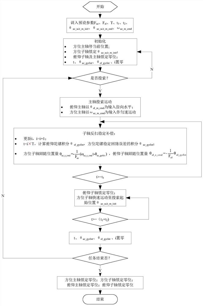
[0092] In this embodiment, the prerequisites for realizing the anti-scanning stability compensation method using the staring detector photoelectric search system under the motor base of the photoelectric equipment are as follows:

[0093] 1. Angular gain F of the sub-axis angular displacement in azimuth and pitch relative to the main axis detection optical system az , F el Has been determined; in this preferred embodiment F az = 2,,

[0094] 2. The running cycle T of the servo control software and the staring time t 1 , reset time t 2 , Azimuth spindle search movement speed ω az_m_cmd , Azimuth sub-axis anti-sweep compensation starting position θ az_sub_m_init , Azimuth sub-axis anti-sweep compensation end position θ az_sub_m_end It has been determined; in this preferred embodiment: T=0.5ms, t 1 = 10ms, t 2 = 10ms, ω az_m_cmd =180° / s, θ az_sub_m_init =0.9°, θ az_sub_m_init =-0.9°.

[0095] 3. The spindle gyro stabilization circuit of the azimuth and pitch composi...


PUM


Abstract

The invention belongs to the technical field of automatic control, and discloses a reverse scanning stability compensation method adopting a staring type detector photoelectric search system under a movable base. An optical axis is stabilized in a pitching direction in a main shaft and sub-shaft composite shaft form. An azimuth main shaft keeps uniform motion in an inertial space, and in a reversescanning compensation stage, an integral value of an azimuth main shaft gyro stabilization loop error is used as an input control instruction of an azimuth sub-shaft position closed loop after passing through a certain gain. In the reset stage, the sub-shaft and the main shaft are aligned in position. According to the invention, the influence of a small finite rotation angle of a sub-axis in thecomposite axis system on the high-precision stable compensation control of the photoelectric equipment is reduced by aligning the sub-axis with the main axis in a reset stage. Through integral response of a sub-shaft to main shaft gyro data in a reverse scanning compensation stage, high-precision isolation of disturbance in a high-speed motion state of a main shaft and a high-speed reverse scanning state of the sub-shaft of the photoelectric search system is realized, the staring precision of the photoelectric search system in the reverse scanning compensation stage is improved, and stable search of a target is realized.

Description

technical field [0001] The invention belongs to the technical field of automatic control, and mainly relates to a control method, in particular to a method for backscanning stability compensation using a two-dimensional reflector unit for a sub-axis of a photoelectric search system using a staring detector under a motor base. Background technique [0002] For staring detectors, "staring" means that the time for the detector to respond to the scene is very long compared with the readout time required for each detector in the array to respond to the signal, that is, the detector "sees" the scene for a long time, while The time required to fetch the response signal of each detector is very short. Usually staring detectors refer to focal plane array detectors (area array detectors), which have higher signal-to-noise ratio and sensitivity than scanning imaging detectors (line array detectors), but their shortcomings are also obvious. Requires a relatively long "stare" time to im...

Claims


Application Information

Patent Timeline
IPC IPC(8): G01S7/481G02B26/10
CPCG01S7/4817G02B26/105
Inventor 刘小强邢军智宋晓明柳井莉杨修林张蕙菁任高辉姚林海孟海江杨永安
Owner 西安应用光学研究所
Why Eureka
Try Eureka