Light splitting system by utilizing electro-optic drive and electro-optic crystal

An electro-optic crystal and spectroscopic system technology, applied in the field of spectroscopic systems, can solve the problems of limiting processing efficiency and weakening of laser single pulse energy dispersion, and achieve the effect of keeping energy constant and meeting the requirements of multi-channel laser processing

Pending Publication Date: 2020-11-06
苏州快光科技有限公司
View PDF2 Cites 0 Cited by
  • Summary
  • Abstract
  • Description
  • Claims
  • Application Information

AI Technical Summary

Problems solved by technology

The disadvantage of this method is that the single pulse energy of the laser is scattered and weakened while splitting the beam. For laser processing applications, the pulse energy of the laser is an important parameter with decisive significance, and its size limits the processing efficiency, quality and material range.

Method used


Image

  • Light splitting system by utilizing electro-optic drive and electro-optic crystal
  • Light splitting system by utilizing electro-optic drive and electro-optic crystal
  • Light splitting system by utilizing electro-optic drive and electro-optic crystal

Examples


Embodiment 1

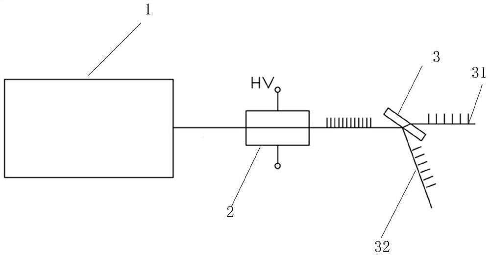
[0026] An embodiment of the present invention provides a spectroscopic system using electro-optic drive and electro-optic crystals, such as figure 1 As shown, the system includes: a laser 1, a first electro-optic crystal 2 and a first polarizer 3;

[0027] Wherein, the laser 1 emits a linearly polarized beam through the first electro-optic crystal 2 and the first polarizer 3 in sequence; a fixed voltage is applied to the first electro-optic crystal 2; the first polarizer 3 divides the linearly polarized beam into a first beam 31 and a second beam 31. Beam 32.

[0028] Through the above system, the electro-optic crystal, high-voltage driving source and polarizer are used to realize the multi-channel and multi-frequency output of the laser, keep the energy unchanged, meet the requirements of multi-channel laser processing, and solve the problem of splitting the laser beam at the same time in the prior art. The dispersion of single pulse energy is weakened, and for laser process...

Embodiment 2

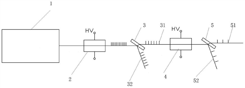
[0035] A spectroscopic system using electro-optic drives and electro-optic crystals, such as figure 2 As shown, it includes: a laser 1, a first electro-optic crystal 2, a first polarizer 3, a second electro-optic crystal 4, and a second polarizer 5;

[0036] Wherein, the laser 1 emits a linearly polarized beam through the first electro-optic crystal 2 and the first polarizer 3 in sequence; a fixed voltage is applied to the first electro-optic crystal 2; the first polarizer 3 divides the linearly polarized beam into a first beam 31 and a second beam 31. Beam 32.

[0037] The first light beam 31 passes through the second electro-optic crystal 4 and the second polarizer 5 in sequence and is divided into a third light beam 51 and a fourth light beam 52 .

[0038] In an embodiment of the present invention, the first light beam 31 is a p-polarized transmitted light beam.

[0039] In an embodiment of the present invention, the second light beam 32 is an S-polarized reflected light...

Embodiment 3

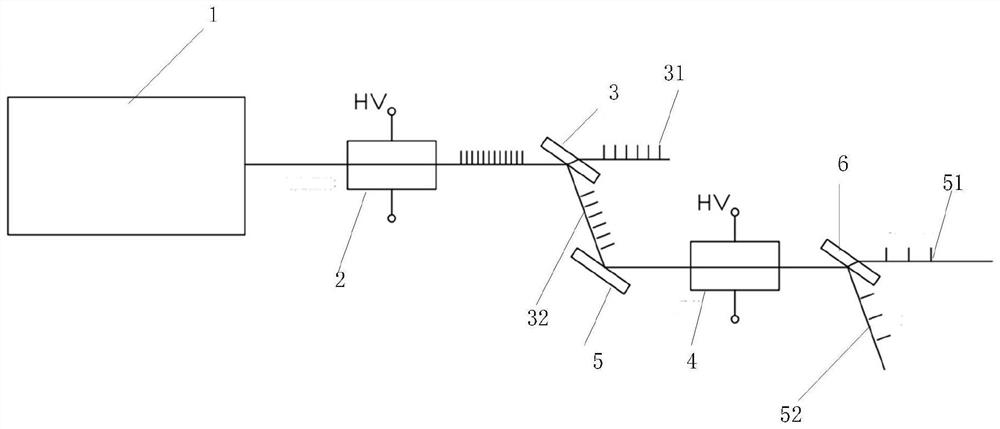
[0045] A spectroscopic system using electro-optic drives and electro-optic crystals, such as image 3 As shown, it includes: a laser 1, a first electro-optic crystal 2, a first polarizer 3, a second electro-optic crystal 4, a second polarizer 5 and a third polarizer 6;

[0046] Wherein, the laser 1 emits a linearly polarized beam through the first electro-optic crystal 2 and the first polarizer 3 in sequence; a fixed voltage is applied to the first electro-optic crystal 2; the first polarizer 3 divides the linearly polarized beam into a first beam 31 and a second beam 31. The light beam 32 ; the second light beam 32 sequentially passes through the second polarizer 5 , the second electro-optic crystal 4 , and the third polarizer 6 to be divided into a third light beam 51 and a fourth light beam 52 .

[0047] In an embodiment of the present invention, the first light beam 31 is a p-polarized transmitted light beam.

[0048] In an embodiment of the present invention, the second ...


PUM


Abstract

The invention discloses a light splitting system by utilizing electro-optic drive and an electro-optic crystal, which is applied to the technical field of light splitting, and comprises a laser, a first electro-optic crystal and a first polarizer, wherein a linearly polarized light beam emitted by the laser sequentially passes through the first electro-optic crystal and the first polarizer; a fixed voltage is applied to the first electro-optical crystal; and the first polarizer divides the linearly polarized light beam into a first light beam and a second light beam. The invention provides a light splitting system by utilizing electro-optic drive and electro-optic crystals, which can realize laser shunt output by changing the voltage of the electro-optic crystals, keep the energy unchangedand meet the multi-path laser processing requirements.

Description

technical field [0001] The invention relates to the field of light splitting technology, and more specifically relates to a light splitting system using electro-optic drive and electro-optic crystals. Background technique [0002] High-power laser technology has been widely used in the laser processing industry, including cutting, welding, marking, etc. In the actual production process, according to the different materials of the workpiece to be processed, the laser energy needs to be changed accordingly to meet the processing requirements. [0003] Conventional spectroscopic systems generally divide a beam of light into several beams and output them with a spectroscope to process multiple targets. The disadvantage of this method is that the single pulse energy of the laser is scattered and weakened while splitting the beam. For laser processing applications, the pulse energy of the laser is an important parameter with decisive significance, and its size limits the processi...

Claims


Application Information

Patent Timeline
Patent Type & Authority Applications(China)
IPC IPC(8): H01S3/10H01S3/115
CPCH01S3/115H01S3/10061
Inventor 艾庆康舒严
Owner 苏州快光科技有限公司
Why Eureka
Try Eureka