Sand stabilization and grass planting device

A technology of planting grass and suits, which is applied in the direction of cultivation, lawn growth, transplanting machinery, etc. It can solve the problems of low work efficiency, troublesome operation, laborious work, etc., and achieve the effect of convenient operation and high work efficiency

Active Publication Date: 2020-11-10
江苏中装建设有限公司
View PDF23 Cites 1 Cited by
  • Summary
  • Abstract
  • Description
  • Claims
  • Application Information

AI Technical Summary

Problems solved by technology

[0005] In order to overcome the disadvantages that people need to constantly move tools to press the grass into the sand, it is laborious, and people need to spread the grass on the sand first, which is troublesome to operate and leads to low work efficiency. The technical problem to be solved is: provide a This is a sand-fixing and grass-planting device that can replace artificially pressing grass into the sand, which is labor-saving, and can lay the grass well and press into the sand, and has high working efficiency.

Method used


Image

  • Sand stabilization and grass planting device
  • Sand stabilization and grass planting device
  • Sand stabilization and grass planting device

Examples


Embodiment 1

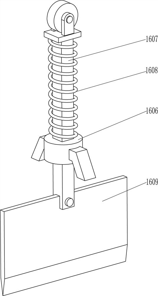
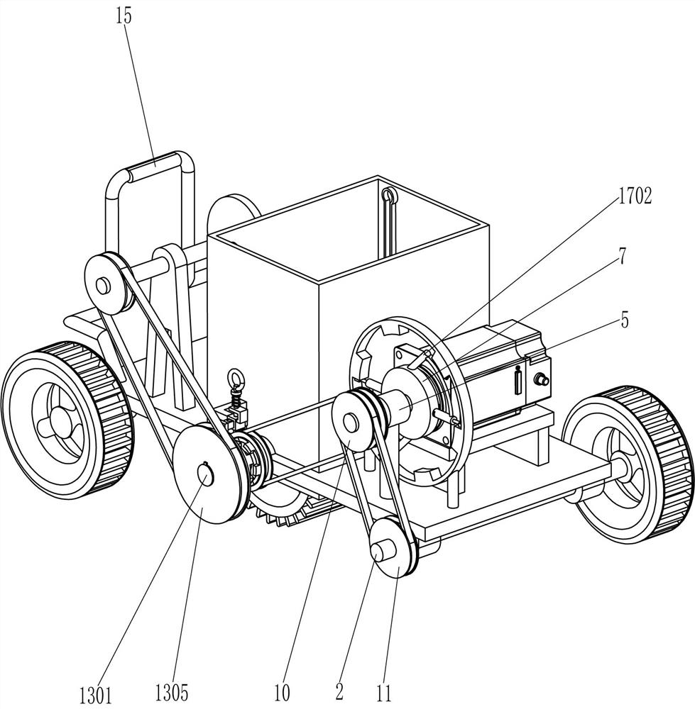
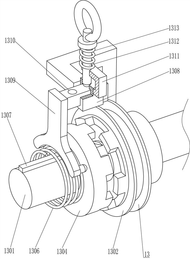
[0025] A device for fixing sand and planting grass, such as figure 1 , figure 2 , image 3 , Figure 4 , Figure 5 and Figure 7As shown, it includes a support plate 1, a first rotating shaft 2, a traveling wheel 3, a servo motor 4, a first supporting sleeve 5, a second rotating shaft 6, a fixed plate 7, a driving block 8, a first piston rod 9, and a double-slot transmission Wheel 10, first transmission wheel 11, first belt 12, drive assembly 13, handle 14, touch switch 15 and planting grass assembly 16, all left and right sides of the bottom of support plate 1 are connected with the first rotating shaft 2 in a rotational manner, the second The front and rear ends of a rotating shaft 2 are fixedly connected with traveling wheels 3, the left side of the top of the support plate 1 is fixedly connected with a handle 14, the upper right side of the handle 14 is fixedly connected with a touch switch 15, and the right side of the top of the support plate 1 is fixedly connected ...

Embodiment 2

[0032] On the basis of Example 1, such as figure 1 , figure 2 and Figure 7 As shown, a brake assembly 17 is also included, and the brake assembly 17 includes a fixed frame 1701, a first cylinder body 1702, a second cylinder body 1703, a second piston rod 1704, a block 1705, an air pipe 1706 and a fourth spring 1707 A first cylinder 1702 is fixedly connected to the middle of the outer top of the fixed disk 7 and the middle of the bottom, the first cylinder 1702 is arranged obliquely, the outer end of the first piston rod 9 is located in the first cylinder 1702 to cooperate with it, and the outer end of the fixed disk 7 The middle parts of the left and right sides are connected with the second cylinder 1703, the second cylinder 1703 is slidingly provided with the second piston rod 1704, and the outer end of the second piston rod 1704 runs through the second cylinder 1703 and is fixedly connected with a block 1705. A fourth spring 1707 is fixedly connected between the inner e...

Embodiment 3

[0035] On the basis of embodiment 1 and embodiment 2, such as Figure 6 As shown, also include placement frame 18, guide rail 19, pressing plate 20, pull bar 21 and sheave 22, support plate 1 top center is equipped with placement frame 18, and placement frame 18 is fixed with guide rail 19 on the front and rear sides, left upper part , between the guide rails 19 on the front and rear sides, there is a sliding pressure plate 20, the pressure plate 20 is in contact with the inner wall of the placement frame 18, the top left middle of the pressure plate 20 is fixedly connected with a pull rod 21, and the middle part of the support plate 1 is connected with a sheave 22 in a rotating manner , the front end of the sheave 22 is fixedly connected to the rear end of the third rotating shaft 1301 .

[0036] First, the operator pulls the pull rod 21 to move upward, and the upward movement of the pull rod 21 drives the pressure plate 20 to move upward. An appropriate amount of grass is p...


PUM


Abstract

The invention relates to a grass planting device, in particular to a sand stabilization and grass planting device. The technical problem to be solved is to provide the sand stabilization and grass planting device, by means of the sand stabilization and grass planting device, grass can be pressed into sand instead of manpower, labor is saved, the grass can be well laid and pressed into the sand, and the working efficiency is high. The sand stabilization and grass planting device comprises a supporting plate and walking wheels, and first rotating shafts are symmetrically and rotationally connected to one side of the supporting plate; and the walking wheels are fixedly arranged at the two ends of the first rotating shafts in a sleeving manner. The sand stabilization and grass planting deviceis moved to the sand where the grass is laid, a clutch block is engaged with a clutch transmission wheel, a touch switch is pressed, a servo motor is started, then the sand stabilization and grass planting device can be moved to press the grass into the sand through a scraper knife, the grass does not need to be pressed into the sand by a person with a tool held with the hands, labor is saved, operation is convenient, and the working efficiency is high.

Description

technical field [0001] The invention relates to a grass planting device, in particular to a sand fixing grass planting device. Background technique [0002] Sandy land refers to land covered by sand and basically without vegetation, including deserts, excluding sandy beaches in water systems. Sandy land is mainly distributed in semi-humid areas, and its formation is mostly caused by local soil parent materials, so it is mainly distributed in the eastern Huanghuaihai Plain And coastal areas, in the sandy land, in order to prevent the sand from flowing freely and being blown away by the wind, grass will be inserted on the sandy land, thereby playing the role of windbreak and sand fixation. [0003] At present, most of the grass is manually pressed into the sand. First, people spread the grass on the sand, and then hold the tool to press the grass into the sand. Due to the large amount of grass, people need to constantly move the tools to move the grass into the sand. It takes...

Claims


Application Information

Patent Timeline
Patent Type & Authority Applications(China)
IPC IPC(8): A01G20/00A01C11/00E02D3/00
CPCA01G20/00A01C11/00A01C11/006E02D3/00Y02A40/22
Inventor 赖日军
Owner 江苏中装建设有限公司
Why Eureka
Try Eureka