
Rear windshield defrosting device

A rear windshield and glass technology, which is applied in the field of auto parts, can solve the problems of slow defogging speed and glass cracking, and achieve the effect of small blocking effect, avoiding cracking, and eliminating uneven heating

Active Publication Date: 2021-07-27
CHONGQING VOCATIONAL COLLEGE OF TRANSPORTATION
View PDF2 Cites 0 Cited by
  • Summary
  • Abstract
  • Description
  • Claims
  • Application Information

AI Technical Summary

Problems solved by technology

[0004] The present invention intends to provide a rear windshield defrosting device to solve the problems of slow defogging speed and glass bursting caused by uneven heating in the existing defogging of the silver paste lines of the rear windshield

Method used


Image

  • Rear windshield defrosting device
  • Rear windshield defrosting device
  • Rear windshield defrosting device

Examples

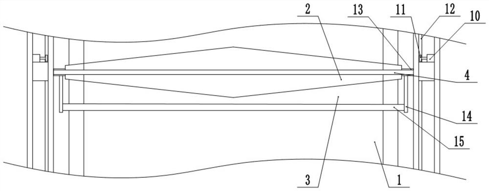
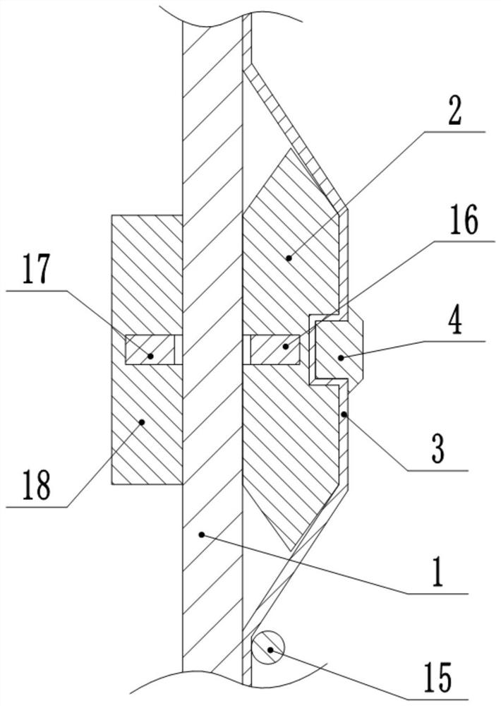

Embodiment

[0024] Such as figure 1 , figure 2 , image 3 and Figure 4 Shown:

[0025] A rear windshield defrosting device, comprising a rear windshield 1 fixed on the vehicle body, vertical slide rails are arranged on both sides of the outer wall of the rear windshield 1, the slide rails are fixed on the vehicle body, and Slidingly connected with sliders, the sliders are provided with driving devices; a transparent film 3 is arranged between the sliders, and the film 3 is closely attached to the rear windshield 1, and the upper and lower ends of the film 3 are fixed on the rear windshield. On the glass 1, a top convex piece 2 is arranged between the film 3 and the rear windshield 1, the two ends of the top convex piece 2 are fixed with connecting blocks 13, and the connecting blocks 13 are respectively fixedly connected with corresponding sliders; A defrosting sheet 4 is arranged on the surface, and the defrosting sheet 4 is located at the upper end of the top convex sheet 2, and t...

specific Embodiment approach

[0026] The forward and reverse motor 10 and the drive motor 7 are started by the PLC controller, the forward and reverse motor 10 drives the drive gear 11 to rotate, and the slider is driven to reciprocate on the slide rail through the engagement between the drive gear 11 and the rack 12 .

[0027] When the slider slides, the top protruding piece 2 is driven to slide through the connecting block 13, and while the top protruding piece 2 is sliding, the top protruding piece 2 continuously lifts up the film 3, deforming the film 3, so that there is a gap between the frost and the film 3. gap, the top protruding piece 2 slides and drives the defrosting piece 4 at the same time, and the defrosting piece 4 is used to scrape off the frost; compared with the existing electric heating defogging method, this scheme has a smaller blocking effect on the field of view; at the same time This scheme does not need to heat the rear windshield 1 itself, fundamentally eliminates the uneven heatin...


PUM


Abstract

The invention relates to the field of auto parts, and specifically discloses a rear windshield defrosting device, which includes a rear windshield fixed on a vehicle body, vertical slide rails are arranged on both sides of the outer wall of the rear windshield, and the slide rails Fixed on the vehicle body, sliders are slidably connected to the slide rails, and driving devices are arranged on the sliders; a transparent film is arranged between the sliders, and the film is closely attached to the rear windshield, and the upper and lower ends of the film It is fixed on the rear windshield, and a top convex piece is arranged between the film and the rear windshield, and connecting blocks are fixed at both ends of the top convex piece, and the connecting blocks are respectively fixedly connected with the corresponding sliders; the outer surface of the film is provided with There is a defrosting sheet, and the defrosting sheet is located at the upper end of the top convex sheet, and the two ends of the defrosting sheet are respectively fixedly connected with the corresponding sliders; Slow defogging speed and glass bursting caused by unevenness.

Description

technical field [0001] The invention relates to the technical field of auto parts, and specifically discloses a rear windshield defrosting device. Background technique [0002] When a car is parked or driven in a cold environment, the rear windshield is prone to frost, which will seriously affect the driver's vision and endanger driving safety. If relying on the manual erasing of the driver and the removal of the rain wiper, it will undoubtedly bring great inconvenience to the driver, and the hard frost is likely to cause damage to the windshield wiper. [0003] At present, in the related art, the rear windshield is defrosted by resistance heating. However, the power of the heating resistor is generally high and it is difficult to carry out precise control, and the heating resistor can only be distributed in a small area of ​​the rear windshield. Therefore, the current heating method has disadvantages such as unstable heating temperature and uneven heating, poor defrosting...

Claims


Application Information

Patent Timeline
Patent Type & Authority Patents(China)
IPC IPC(8): B60S1/02B60J1/00B60S1/44
CPCB60J1/002B60S1/023B60S1/44
Inventor 程鹏
Owner CHONGQING VOCATIONAL COLLEGE OF TRANSPORTATION
Learn More