
Supporting leg structure of pile driver for building

A pile driver and construction technology, applied in construction, infrastructure engineering, sheet pile walls, etc., can solve the problems of inability to achieve precise adjustment, low shock and decompression effect, and affect the piling effect, so as to improve the piling effect, Effect of reducing shaking and ensuring stability

Inactive Publication Date: 2020-11-10
徐州祥瑞工程机械科技有限公司
View PDF7 Cites 0 Cited by
  • Summary
  • Abstract
  • Description
  • Claims
  • Application Information

AI Technical Summary

Problems solved by technology

[0003] In the case of using the outrigger structure of a traditional construction pile driver, the prior art has the following problems: 1. Accurate adjustment cannot be achieved, movement is difficult, and there are few satisfactory working environments
2. The effect of cushioning and decompression is low, and there will be shaking, which will affect the piling effect

Method used


Image

  • Supporting leg structure of pile driver for building
  • Supporting leg structure of pile driver for building
  • Supporting leg structure of pile driver for building

Examples


Embodiment approach

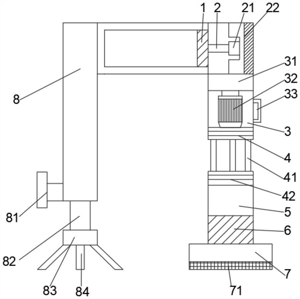
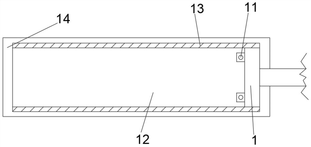
[0022] As a preferred embodiment of the present invention, two installation buttons 11 are connected to the left side of the installation plate 1, and the two installation buttons 11 are distributed symmetrically with the push rod 2 as the center. The moving cavity 12 is provided with sliding grooves 13 on the upper and lower sides of the moving cavity 12, and the upper side of the sliding groove 13 is provided with a mounting frame 14, which facilitates movement and speeds up work efficiency.

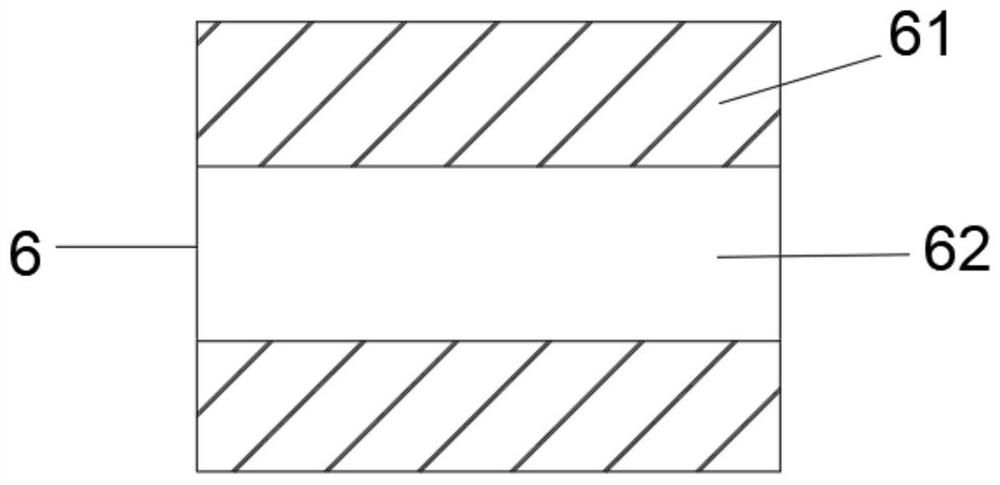
[0023] As a preferred embodiment of the present invention, a connecting plate 62 is arranged in the middle of the decompression pad 6, and cushioning pads 61 are installed on the upper and lower sides of the connecting plate 62 to avoid deformation and movement caused by excessive pressure. , to improve security.

[0024] As a preferred embodiment of the present invention, a rotary switch 81 is provided on the left side of the auxiliary bracket 8, a support rod 82 is connected to the l...


PUM


Abstract

The invention discloses a supporting leg structure of a pile driver for a building. The supporting leg structure comprises a mounting plate, a pushing rod, an upper supporting rod, a spring plate, a lower supporting rod, a pressure reducing pad, a bottom plate and an auxiliary support; the pushing rod is fixedly connected to the right side of the mounting plate, a retracting rod is arranged at theright end of the pushing rod, and a telescopic machine is fixedly mounted at the right end of the retracting rod; and the lower side of the telescopic machine is connected with the upper supporting rod, a motor is installed in the middle of the upper supporting rod, the motor is in transmission connection with a rotating disc through an output shaft, and a control panel is arranged at the right end of the upper supporting rod. By the arrangement of the mounting plate, a moving cavity and the telescopic machine, a pile head can transversely move in the moving cavity, and meanwhile, the motor and the rotating disc are arranged, so that the pile head can rotate to change the position, the pile head can be accurately adjusted, moving is convenient, adaptation to various working scenes is achieved, the working efficiency is improved, the structural stability is further guaranteed, and the piling effect is improved.

Description

technical field [0001] The invention relates to the technical field of outrigger structures, in particular to an outrigger structure of a construction pile driver. Background technique [0002] In the process of building construction, piles are usually driven into the ground to make the foundation of the building firm. This kind of piling machine is collectively called a pile driver. A common pile driver is composed of a pile hammer, a pile frame and ancillary equipment. According to different power forms It is divided into drop hammer piling, steam hammer piling and diesel hammer piling, because if the ground buildings are to be built on the ground, the ground will bear a lot of pressure, so it is necessary to ensure that the ground has enough strength to resist the pressure, which is often difficult to do Therefore, it is necessary to strengthen the ground bearing the building or improve the bearing mode of the ground, so it is thought of driving piles on the foundation, s...

Claims


Application Information

Patent Timeline
Patent Type & Authority Applications(China)
IPC IPC(8): E02D7/06E02D7/16
CPCE02D7/06E02D7/16
Inventor 吕爱荣
Owner 徐州祥瑞工程机械科技有限公司
Learn More