
Annular magnetic rod hydraulic displacement transmission device for solar tracking system

A solar tracking and transmission technology, applied in solar heating systems, transmissions, fluid transmissions, etc., can solve the problems of high maintenance cost of belt transmission, complex comprehensive mechanism, and high maintenance cost, and achieve low cost, stable transmission, and installation. Convenient time-saving effect

Pending Publication Date: 2020-11-10
北京中科电气高技术有限公司
View PDF0 Cites 0 Cited by
  • Summary
  • Abstract
  • Description
  • Claims
  • Application Information

AI Technical Summary

Problems solved by technology

The maintenance cost of the belt drive is a bit high for field work equipment. At present, in the solar tracking system, whether it is the azimuth axis or the pitch axis, the conventional gear transmission is used, and the gear, the worm gear, the worm and the electric motor (motor) are used to cooperate. The drive requires a telescopic mechanism, a sealing mechanism, a self-locking mechanism, a transmission mechanism, and an electric control device. As we all know, compared with hydraulic transmission, motor-driven gear transmission has a more complex comprehensive mechanism, takes up a lot of space, and is difficult to manufacture. Due to the wear and tear of the gears during operation, the maintenance cost is high; in addition, the motor must exert force when maintaining a static state and changing the displacement, and the operating cost is high

Method used


Image

  • Annular magnetic rod hydraulic displacement transmission device for solar tracking system
  • Annular magnetic rod hydraulic displacement transmission device for solar tracking system
  • Annular magnetic rod hydraulic displacement transmission device for solar tracking system

Examples


Embodiment

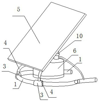
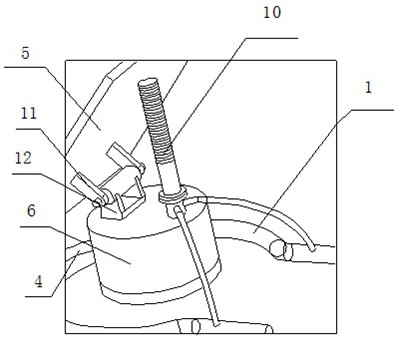
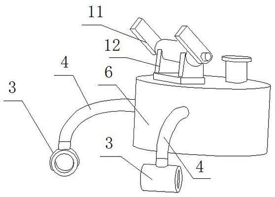
[0040] Embodiment: An annular magnetic rod hydraulic displacement transmission device for a solar tracking system, including a magnetic rod, a hydraulic transmission mechanism, and a rotary displacement mechanism. The magnetic rod 3 outside the tube, the magnetic rod is to transfer the movement of the liquid in the tube 1 to the magnetic rod 3 outside the tube through the magnetic rod 2 in the tube, so as to realize the air transmission; the hydraulic transmission mechanism includes hydraulic oil circuit, hydraulic oil, isolation Pipe 1 and transmission rod 4, the hydraulic oil circuit is connected with spacer pipe 1, the hydraulic transmission mechanism pushes the magnetic rod 2 inside the pipe through the hydraulic oil to drive the magnetic rod outside the pass to move, and at the same time the magnetic rod 3 outside the pipe drives the rotation displacement mechanism above the transmission rod 4 The solar collector plate 5 for collecting solar energy realizes rotational disp...


PUM


Abstract

The invention discloses an annular magnetic rod hydraulic displacement transmission device for a solar tracking system. The annular magnetic rod hydraulic displacement transmission device comprises magnetic rods, hydraulic transmission mechanisms and a rotary displacement mechanism, wherein the magnetic rods comprise in-pipe magnetic rods arranged inside separation pipes and out-pipe magnetic rodsarranged outside the separation pipes, and the magnetic rods are used for transmitting the movement of the liquid inside the separation pipes to the out-pipe magnetic rods through the in-pipe magnetic rods so as to realize air separation transmission; each hydraulic transmission mechanism comprises a hydraulic oil way, hydraulic oil, one separation pipe and a transmission rod, the hydraulic oil ways are connected with the separation pipes, and the hydraulic transmission mechanisms push the in-pipe magnetic rods through the hydraulic oil to drive the out-pipe magnetic rods to move, and meanwhile, the out-pipe magnetic rods drive a solar energy collecting plate for collecting solar energy on the rotary displacement mechanism through the transmission rods to realize rotary displacement; andthe rotary displacement mechanism comprises a rotary transmission shaft and a fixed bearing column. The annular magnetic rod hydraulic displacement transmission device for the solar tracking system adopts a non-contact transmission mode, and uses the mutual attraction or mutual repulsion effect of magnetic force to achieve non-contact transmission of hydraulic force.

Description

technical field [0001] The invention relates to a transmission device, in particular to an annular magnetic rod hydraulic displacement transmission device of a solar tracking system. Background technique [0002] As the source of earth's energy, solar energy has the advantages of abundant resources, unlimited reserves, flexible mining, inexhaustible supply, inexhaustible use, development and utilization everywhere, no need for transportation, and no pollution to the environment. It occupies a leading position in the long-term energy strategy It has an important position, and the development and utilization of solar energy has a huge market prospect. It not only brings good social and environmental benefits, but also has good economic benefits. [0003] Our concentrated use of solar energy can be roughly divided into two types: photothermal application and photovoltaic application, but the utilization efficiency of these two methods for solar energy is still low. How to achie...

Claims


Application Information

Patent Timeline
Patent Type & Authority Applications(China)
IPC IPC(8): F16H43/00F15B21/08F24S50/20H02S20/30H02S20/32H02K49/00
CPCF16H43/00F15B21/087F24S50/20H02S20/30H02S20/32H02K49/00Y02E10/47Y02E10/50
Inventor 张文俊
Owner 北京中科电气高技术有限公司
Learn More